1
2
3
4
5
6
7
8
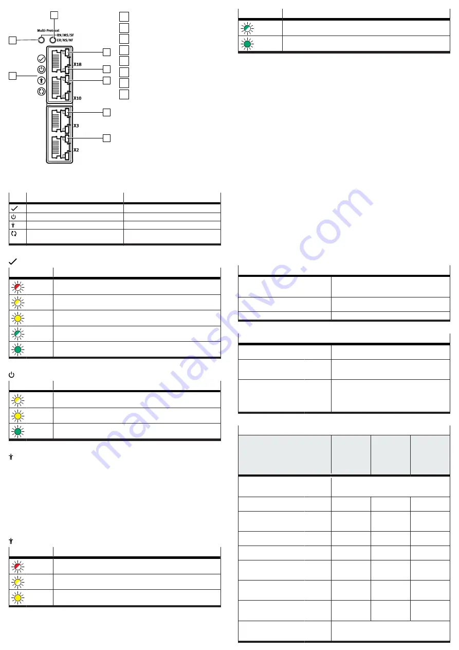
Fig. 12: LEDs on the front
1
Device status (4 LEDs)
2
RN/MS/SF (example CMMT-AS-...-MP)
3
ER/NS/NF (example CMMT-AS-...-MP)
4
Ethernet interface activated [X18]
5
Communication activity [X18]
6
Sync interface activated [X10]
7
Encoder status, encoder interface [X3]
8
Encoder status, encoder interface [X2]
11.1.1
Device status displays
LED
Identifier
Brief description
Status LED
Indicates the general device status
Power LED
Indicates the status of the power supply
Safety LED
Indicates the status of the safety equipment
Application status LED
Indicates the identification sequence and is
reserved for future extensions
Tab. 46: Device status LEDs (status, power, safety and application status LEDs)
Status LED, display of the device status
LED
Meaning
flashes
red
An error is present.
flashes
yellow
A warning is present, or the servo drive is currently performing a firmware
update.
yellow
light
The servo drive is in the initialisation phase.
flashes
green
The servo drive is ready, and the power stage is switched off (Ready).
green
light
The power stage and the closed-loop controller are enabled.
Tab. 47: Status LED
Power LED, status of the power supply
LED
Meaning
flashes
yellow
The logic voltage and AC supply are present. The intermediate circuit is being
charged.
yellow
light
The logic voltage supply is present, but the AC supply is lacking.
green
light
The logic voltage supply is present, and the intermediate circuit is charged.
Tab. 48: Power LED
Safety LED, status of the safety equipment
Malfunctions of the safety sub-functions are detected and displayed in the func-
tional device. The following are detected:
–
Safety sub-functions requested via 1 channel (discrepancy monitoring)
–
Internal device errors that lead to pulse monitoring not being switched off or
only switched off on one channel
–
Errors in the brake outputs or the external wiring that result in voltage being
present on the brake output even though the safety sub-function SBC has been
requested
Malfunctions are externally reported by the functional part, including via the
additional communication interfaces (bus, commissioning software).
Safety LED, status of the safety engineering
LED
Meaning
flashes
red
Error in the safety part or a safety condition has been violated.
flashes
yellow
The safety sub-function has been requested but is not yet active.
yellow
light
The safety sub-function has been requested and is active.
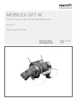
LED
Meaning
flashes
green
Power stage, brake outputs and safety diagnostic outputs are blocked (safety
parameterisation is running).
green
light
Ready, no safety sub-function has been requested.
Tab. 49: Safety LED
11.2
Repair
Repair or maintenance of the product is not permissible. If necessary, replace the
complete product.
1. If there is an internal defect: Always replace the product.
2. Send the defective product unchanged, together with a description of the
error and application, back to Festo.
3. Check with your regional Festo contact person to clarify the conditions for the
return shipment.
12
Disassembly
Disassemble in reverse order of installation.
Before disassembly
1. Switch off the power supply at the main switch.
2. Secure the system against accidental reactivation.
3. Wait at least 5 minutes until the intermediate circuit has discharged.
4. Let the device cool down to room temperature.
5. Before touching the power connections [X6A], [X9A], [X9B], check to ensure
they are free of voltage.
6. Disconnect all electrical cables.
To dismount the device
•
Loosen retaining screws (2x) and remove the device from the mounting sur-
face.
13
Technical data
13.1
Technical data, safety engineering
Approval information, safety engineering
Type test
The functional safety engineering of the product has
been certified by an independent testing body, see EC-
type examination certificate
Certificate issuing authority
TÜV Rheinland, Certification Body of Machinery, NB
0035
Certificate no.
01/205/5640.00/18
Tab. 50: Approval information, safety engineering
General safety reference data
Request rate in accordance
with EN 61508
High request rate
Reaction time when the
safety sub-function is
requested
[ms]
<
10 (applies to STO and SBC)
Error reaction time (how long
it takes for the diagnostic
output status to become cor-
rect once the safety sub-func-
tion has been requested)
[ms]
<
20 (applies for STA and SBA)
Tab. 51: Safety reference data and safety specifications
Safety reference data for the safety sub-function STO
Circuitry
Without high
test pulses,
without or
with STA
evaluation
With high
test pulses
and with STA
evaluation
1)
With high
test pulses
and without
STA evalua-
tion
Safety sub-function
in accordance with
EN 61800-5-2
Safe torque off (STO)
Safety integrity level in
accordance with EN 61508
SIL 3
SIL 3
SIL 2
SIL claim limit for a sub-
system in accordance with
EN 62061
SIL CL 3
SIL CL 3
SIL CL 2
Category in accordance with
EN ISO 13849-1
Cat. 4
Cat. 4
Cat. 3
Performance level in accord-
ance with EN ISO 13849-1
PL e
PL e
PL d
Probability of dangerous
failure per hour in accord-
ance with EN 61508, PFH
[1/h]
3.70 x 10
–11
9.40 x 10
–11
5.90 x 10
–10
Mean time to dangerous
failure in accordance with
EN ISO 13849-1, MTTF
d
[a]
2400
1960
1960
Average diagnostic cov-
erage in accordance with
EN ISO 13849-1, DC
AVG
[%]
97
95
75
Operating life (mission
time) in accordance with
EN ISO 13849-1, T
M
[a]
20


