
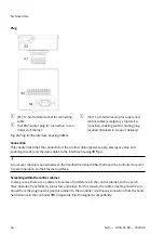

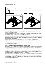
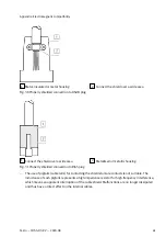


Emergency stop in normal position (not
pressed)
Emergency stop pressed
Tab. 32 Emergency stop
The emergency stop must therefore not serve as a predominant safety device, but is intended exclus-
ively to cover any residual risks.
Instead of the emergency stop, locking protective doors, light barriers, two-hand switches or 3-posi-
tion enabling switches can be used depending on the operating mode.
When the emergency stop switch is actuated, the entire machine or all machines connected to form a
system must be brought into a safe state, e.g. by shutting off the energy of the hazardous drives (stop
categories 0 or 1 to EN 60204-1).
Unlocking the emergency stop switch must not cause an uncontrolled restart of the machine.
Regardless of whether an emergency stop is present on a handheld terminal or not, permanently
installed, easily identifiable and easily accessible emergency stop switches must be installed at selec-
ted locations around the machine.
14.9
Control elements for stopping in an emergency
The Machinery Directive does not make any detailed requirements regarding the colours of the control
elements for stopping in an emergency. The requirement is: "The command device must have clearly
identifiable, easily visible and quickly accessible actuators".
Emergency stop switches are normally coloured red and yellow. The special design has the purpose of
a signal effect, and is intended to ensure that everyone, even untrained persons, can identify the con-
trol element as the device for eliminating a danger in an emergency.
It is therefore absolutely essential that a safe status can be initiated at any time and in any operating
mode without further knowledge of the machine (see also EN ISO 13850). Changing the ready status
of an emergency stop switch is not permissible, as this can lead to incorrect actions and life-threaten-
ing loss of time in panic situations.
Appendix: Safety of machinery
55
Festo — CDSA-D3-RV — 2020-08


