SUN P N
45
EN
cod. 3541F710 - Rev. 00 - 05/2017
Burner setting
1. Connect a combustion analyser to the boiler outlet and leave the burner working at max. for 30 minutes; in the mean-
time check the fume extraction duct.
2.
MAKE SURE THE COMBUSTION CHAMBER IS IN NEGATIVE PRESSURE
3. Check the combustion at max. burner power (adjusted according to boiler rated output).
4. Combustion parameters:
•
O
2
between 5% and 9%
•
CO between 150 and 1000 ppm
NOTE
The CO value is affected by the quality of the pellets, the amount of dirt in the combustion head, and boiler draft.
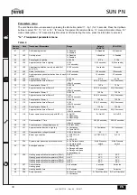
If necessary, for burner calibration, vary the fan setpoint by modifying the relevant parameter (see par.
“Parameters
menu” on page 34
and
Table 2, “Burner max. power,” on page 32
).
5. After checking combustion at maximum power, also check the other burner steps: repeating the procedure de-
scribed above and reducing the value of the parameter u05 down to 1 (see par. Parameters Menu and Table 2 in
par. 2.4)
6. To operate the burner in Modulating mode, it is necessary to modify the parameter t18 (see par. Parameters Menu)
7. Restore the burner maximum power parameter u05 to the desired value (adjusted according to boiler nominal power)
3.2 Maintenance
Checks and controls
A
Periodically check the cleanness of the burner parts which will tend to get dirty depending on the quality of the
pellets or due to incorrect burner adjustment.
A
Periodically check the pellet hopper and remove dust from the bottom. An excessive amount of dust can affect
the proper supply of fuel to the burner.
The burner requires periodical maintenance which must be performed by qualified personnel at least once a year.
The basic operations to carry out are:
•
check and cleaning of the internal parts of the burner and boiler as indicated in the following sections;
•
complete combustion analysis (after at least 10 minutes' operation) and check of correct settings;
Opening the casing and removing the burner
B
Before carrying out any checking or cleaning inside the burner, disconnect the power to the burner by means
of the main system switch.
To open
Undo the screws (A) and remove the casing (B). The internal components, motor, damper, etc., are directly accessible.
fig. 12 - Casing opening
A
B
Summary of Contents for SUN P N Series
Page 99: ...SUN P N 100 BG B 7 6 52 5 5 8 56 B A cod 3541F710 Rev 00 05 2017...
Page 102: ...SUN P N 103 BG cod 3541F710 Rev 00 05 2017 1 1 4 1 d2 2 6 1 4 1 d1 3 1 3 4 B sez 1 3...
Page 109: ...SUN P N 110 BG cod 3541F710 Rev 00 05 2017 1 5 B...
Page 116: ...SUN P N 117 BG cod 3541F710 Rev 00 05 2017 3 FERROLI 3 1 A 1 11 11 sez 2 4 1...
Page 118: ...SUN P N 119 BG cod 3541F710 Rev 00 05 2017 C D E 13...
Page 150: ...SUN P N 151 GR cod 3541F710 Rev 00 05 2017 1 1 4 1 d2 2 6 1 4 1 d1 3 1 3 4 B sez 1 3...
Page 157: ...SUN P N 158 GR cod 3541F710 Rev 00 05 2017 1 5 B...
Page 164: ...SUN P N 165 GR cod 3541F710 Rev 00 05 2017 3 FERROLI 3 1 pellet A 1 11 11 pellet sez 2 4 1...
Page 166: ...SUN P N 167 GR cod 3541F710 Rev 00 05 2017 12 C D E 13 A B...
Page 195: ...SUN P N 196 SR B COUNTRIES OF DESTINATION IT RO GB B A cod 3541F710 Rev 00 05 2017...
Page 198: ...SUN P N 199 SR cod 3541F710 Rev 00 05 2017 1 1 4 1 d2 2 6 1 4 1 d1 3 1 3 4 B sez 1 3...
Page 205: ...SUN P N 206 SR cod 3541F710 Rev 00 05 2017 1 5 B...
Page 212: ...SUN P N 213 SR cod 3541F710 Rev 00 05 2017 3 FERROLI 3 1 A 1 11 11 sez 2 4 1...
Page 214: ...SUN P N 215 SR cod 3541F710 Rev 00 05 2017 C D E 13...
Page 219: ......


