background image

SUN P N

130

HR

cod. 3541F710  -  Rev. 00  -  05/2017

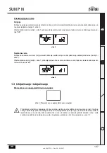
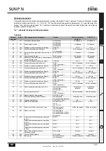
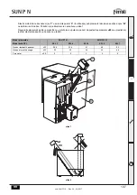
Trenutna snaga plamenika (korak) i stanje plamena

Pritisnite tipku Info (detalj 11 - slika 1) do prikaza informacija 

u07

 na izborniku korisni

þ

kih postavki.

Pritisnite tipku Unesi (detalj 8 - slika 1): prikazuje se trenutna snaga plamenika (korak) i stanje plamena.

1 =

 Minimalna snaga

5 =

 Maksimalna snaga

0/FH=

 Tijekom predventiliranja/Nakon ventiliranja (post-ventilacija)

6=

 Tijekom post-ventilacije2

Pritisnite tipku Unesi (detalj 8 - slika 1) za povratak na popis parametara.
Zatim pritisnite tipku Info (detalj 11 - slika 1) za izlazak iz samog izbornika.

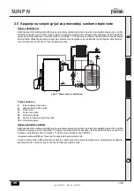
Reguliranje temperature okoline (sa sobnim termostatom u dodatnoj opremi)

Postavite željenu temperaturu u prostorijama pomo

ü

u sobnog termostata. U slu

þ

aju da sobni termostat nije prisutan,

kotao održava u sustavu temperaturu podešene postavne vrijednosti polaznog voda sustava.

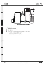
Reguliranje temperature okoline (s daljinskim vremenskim upravlja

þ

em u dodatnoj opremi)

Podesite pomo

ü

u daljinskog vremenskog upravlja

þ

a željenu temperaturu okoline unutar prostorija Plamenik 

ü

e reguli-

rati vodu u sustavu ovisno o željenoj temperaturi okoline. Za rad s daljinskim vremenskim upravlja

þ

em, vidjeti odgova-

raju

ü

e upute za uporabu.

Podešavanja s daljinskog vremenskog upravlja

þ

a

A

Ako je plamenik spojen s daljinskim vremenskim upravlja

þ

em (u dodatnoj opremi), potrebno je izmijeniti para-

metar “u06” (vidi *** 'Metodologija rada plamenika' on page 129 ***); prethodno opisanim reguliranjima upravlja
se na na

þ

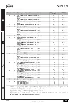
in opisan u tabela 3.

Tabela. 3

Reguliranje temperature grijanja

Reguliranje se može izvršiti s izbornika Daljinskog vremenskog upravlja

þ

a i s plo

þ

e komandi 

plamenika.

Reguliranje temperature sanitarne vode

Reguliranje se može izvršiti s izbornika Daljinskog vremenskog upravlja

þ

a i s plo

þ

e komandi 

plamenika.

Izmjena Ljeto/Zima

Na

þ

in rada Ljeto ima prioritet ako pristigne zahtjev za grijanjem s Daljinskog vremenskog 

upravlja

þ

a.

Izbor Eko/Komfor

Odabir se može izvršiti samo s plo

þ

e komandi plamenika

Isklju

þ

ivanje plamenika (off)

Na

þ

in rada off mogu

ü

 je samo s daljinskog upravlja

þ

a.

Summary of Contents for SUN P N Series

Page 1: ...LA MANUTENZIONE EN INSTRUCTIONS FOR USE INSTALLATION AND MAINTENANCE ES INSTRUCCIONES DE USO INSTALACI N Y MANTENIMIENTO RO INSTRUC IUNI DE UTILIZARE INSTALARE I NTRETINERE BG HR UPUTE ZA UPORABU POST...

Page 2: ...utenzione disinserire l apparecchio dalla rete di alimentazione agendo sull interruttore dell impianto e o attraverso gli appositi organi di intercettazione In caso di guasto e o cattivo funzionamento...

Page 3: ...2 Installazione in caldaia 13 2 3 Collegamenti elettrici 16 2 4 Alimentazione combustibile 16 2 5 Collegamento ad un bollitore esterno per la produzione di acqua calda sanitaria 17 3 Servizio e manut...

Page 4: ...x ed una fiamma molto silenziosa Il bruciatore predisposto per il collegamento ad un bollitore esterno per acqua calda sanitaria opzionale In questo manuale tutte le funzioni relative la produzione di...

Page 5: ...el rubinetto part 6 fig 1 Il display multifunzione part 4 fig 1 visualizza la temperatura del sensore sanitario e durante il tempo di attesa sa nitario la scritta d1 fig 3 1 3 Accensione e spegnimento...

Page 6: ...en utente Per accedere al men delle impostazioni utente sar necessaria una pressione del tasto Info part 11 fig 1 Sono disponibili 7 parametri ed una informazione indicati dalla lettera u Tabella 1 Pr...

Page 7: ...tasti part 9 e 10 fig 1 per impostare la modalit Economy 0 o Comfort 1 Premere il tasto Invio part 8 fig 1 per confermare l impostazione Successivamente premere il tasto Info part 11 fig 1 per uscire...

Page 8: ...l cronocomando remoto la temperatura ambiente desiderata all interno dei locali Il bruciatore rego ler l acqua impianto in funzione della temperatura ambiente richiesta Per quanto riguarda il funziona...

Page 9: ...00 10 secondi 38 3 8 secondi 40 4 0 secondi 12 t12 Setpoint ventilatore a Potenza 3 0 200 Pa 120 Pa 100 Pa 13 t13 Tempo attivazione coclea a Potenza 3 0 100 100 10 secondi 46 4 6 secondi 45 4 5 second...

Page 10: ...33 Post Circolazione pompa sanitario 0 20 minuti 4 minuti 4 minuti 34 P34 Tempo attesa sanitario 0 20 minuti 4 minuti 4 minuti 35 P35 Massimo setpoint utente sanitario P25 1 Massimo setpoint utente sa...

Page 11: ...ta delle anomalie sufficiente una pressione del tasto Invio Per tornare al Men Service sufficiente una pressione del tasto Info L uscita dal Men Service della scheda avviene premendo il tasto Info per...

Page 12: ...ifornimento del combustibile prima del suo totale esaurimento per evitare il funzionamento irregolare del bruciatore Fare attenzione che il locale in cui installato il bruciatore oltre che privo di og...

Page 13: ...possono funzionare assieme le aperture di aereazione devono essere dimensionate per il funzionamento contemporaneo di tutti gli apparecchi Il luogo di installazione deve essere privo di oggetti o mat...

Page 14: ...it A termine del montaggio del kit in caldaia montare il bruciatore Fissare il boccaglio L con le viti M e il bruciatore con il dado N Collegare il cavo E ai morsetti 20 e 21 e il cavo T al sensore V...

Page 15: ...ario rispettare la quota indicata nella fig 7 Regolare il bruciatore come previsto dal relativo manuale istruzioni in particolare impostare il parametro u05 sulla cen traliana del bruciatore come ripo...

Page 16: ...materiali non combustibile all interno del bruciatore Per distinguere il pellet di qualit bene seguire alcuni accorgimenti Deve essere costituito da cilindri di diametro costante ed avere una superfic...

Page 17: ...nite a parte Effettuare collegamenti elettrici come indicato nello schema elettrico vedi fig 17 E necessario l utilizzo di una sonda FERROLI Il sistema di controllo caldaia alla successiva accensione...

Page 18: ...sario l utilizzo di una sonda FERROLI Modificare parametro P25 del Men Parametri Trasparenti a 3 Il sistema di controllo caldaia alla successiva accensione riconosce la presenza della sonda bollitore...

Page 19: ...rima di accendere il bruciatore Controllare che il bruciatore sia fissato correttamente in caldaia con le tarature preliminari indicate precedentemente Accertarsi che caldaia ed impianto siano stati r...

Page 20: ...ssario modificare il parametro t18 vedi paragrafo Men Parametri 7 Ripristinare il parametro potenza massima del bruciatore u05 al valore desiderato regolato in base alla potenza no minale della caldai...

Page 21: ...interno del ventilatore e sulle pale della girante non vi sia accumulo di polvere riduce la portata d aria e causa conseguentemente combustione inquinante Testa di combustione Verificare che tutte le...

Page 22: ...za in cortocircuito Sostituire fotoresistenza Luce estranea investe lafotoresistenza Eliminare fonte di luce Parametri accensione non corretti Verificare parametri accensione A03 Anomalia cablaggio Po...

Page 23: ...N 23 IT cod 3541F710 Rev 00 05 2017 4 CARATTERISTICHE E DATI TECNICI 4 1 Dimensioni fig 14 Dimensionale SUN P7 N fig 15 Dimensionale SUN P12 N 180 6 0 250 312 217 447 165 282 250 337 210 490 325 165 2...

Page 24: ...i Unit SUN P7 N SUN P12 N Codici identificativi 0U2F6DXA 0U2F8DXA Portata Termica max kW 34 1 55 0 Q Portata Termica min kW 13 7 30 0 Q Portata Combustibile max kg h 7 2 11 6 Portata Combustibile min...

Page 25: ...rcolatore riscaldamento non fornito 34 Sensore temperatura riscaldamento 42 Sensore di temperatura sanitario opzionale 49 Termostato di sicurezza caldaia 72 Termostato ambiente opzionale 95 Valvola de...

Page 26: ...portatenelpresenteCer cato Gliinterven ingaranzianon modi cano la data di decorrenza della garanzia e non prolungano la durata della stessa Esclusioni Sono esclusi dalla presente garanzia i dife di co...

Page 27: ...acturer s instructions Before carrying out any cleaning or maintenance op eration disconnect the unit from the electrical power supply using the switch and or the special cut off de vices In case of a...

Page 28: ...eral Instructions 38 2 2 Installation in boiler 38 2 3 Electrical connections 41 2 4 Fuel supply 41 2 5 Connection to an external tank for domestic hot water production 42 3 Service and maintenance 44...

Page 29: ...es low CO and NOx emissions and a very quiet flame The burner is arranged for connection to an external domestic hot water storage tank optional In this manual all the functions regarding domestic hot...

Page 30: ...d by activation of the faucet detail 6 fig 1 The multifunction display detail 4 fig 1 shows the DHW sensor temperature and during DHW standby time the mes sage d1 fig 3 1 3 Lighting and shutdown Burne...

Page 31: ...1 4 Adjustments User menu To access the user settings menu press the Info button detail 11 fig 1 7 parameters and information indicated by the letter u are available Table 1 By pressing the Info butto...

Page 32: ...r u04 is displayed Use the buttons details 9 and 10 fig 1 to set Economy 0 or Comfort 1 mode Press Enter detail 8 fig 1 to confirm the setting Then press the Info button detail 11 fig 1 to exit the me...

Page 33: ...r control Using the remote timer control set the required temperature in the rooms The burner will adjust the system water ac cording to the required room temperature For operation with remote timer c...

Page 34: ...3 Auger activation time at Power 3 0 100 100 10 seconds 46 4 6 seconds 45 4 5 seconds 14 t14 Fan setpoint at Power 4 0 200 Pa 150 Pa 120 Pa 15 t15 Auger activation time at Power 4 0 100 100 10 seconds...

Page 35: ...inutes 35 P35 DHW user max setpoint P25 1 DHW user max setpoint P25 2 55 65 C 65 C 65 C DHW user max setpoint P25 3 55 65 C 65 C 65 C DHW user max setpoint P25 4 36 P36 No function P25 1 Hot water tan...

Page 36: ...vice Menu just press the Info button To exit the card Service Menu press the Info button for 10 seconds or exiting will be automatic after 15 minutes rE History Reset By pressing Enter for 3 seconds i...

Page 37: ...avoid irregular burner operation it is advisable to top up the fuel before it finishes Make sure the room where the burner is installed is free of flammable materials or objects corrosive gases and v...

Page 38: ...he same room the ventilation openings must be sized for simultaneous operation of all the units The place of installation must be free of flammable materials or objects corrosive gases dusts or volati...

Page 39: ...ng the kit in the boiler fit the burner Secure the nozzle L with the screws M and the burner with the nut N Connect the cable E to the terminals 20 and 21 and the cable T to the sensor V and to the te...

Page 40: ...ct the distance given in the fig 7 Adjust the burner as required by the instruction manual and in particular set the parameter u05 on the burner controller as indicated in the table fig 7 fig 8 Burner...

Page 41: ...wdust and operation shutdowns due to sedimentation of unburnt materials inside the burner To identify quality pellets it is advisable to proceed as follows They must be cylinders of constant diameter...

Page 42: ...be supplied separate ly Carry out the electrical connections as shown in the wiring diagram see fig 17 A FERROLI probe must be used At the next lighting the boiler control system detects the hot wate...

Page 43: ...ng diagram see fig 17 A FERROLI probe must be used Change parameter P25 of the Transparent Parameters Menu to 3 At the next lighting the boiler control system detects the hot water tank probe and auto...

Page 44: ...vices or parts of the burner Before lighting the burner Make sure the burner is correctly fixed in the boiler with the preliminary settings indicated above Make sure the boiler and system are filled w...

Page 45: ...ssary to modify the parameter t18 see par Parameters Menu 7 Restore the burner maximum power parameter u05 to the desired value adjusted according to boiler nominal power 3 2 Maintenance Checks and co...

Page 46: ...arts and components Fan Make sure no dust has accumulated inside the fan and on the blades it reduces the air flow thus causing pollutant combustion Combustion head Make sure all parts of the combusti...

Page 47: ...ters A02 Shutdown for parasite flame Photoresistance short circuit Replace the photoresistance Extraneous light strikes the photoresistance Eliminate the light source Incorrect ignition parameters Che...

Page 48: ...48 EN cod 3541F710 Rev 00 05 2017 4 TECHNICAL DATA AND CHARACTERISTICS 4 1 Dimensions fig 14 Dimensional SUN P7 N fig 15 Dimensional SUN P12 N 180 6 0 250 312 217 447 165 282 250 337 210 490 325 165...

Page 49: ...6 10 Data Unit SUN P7 N SUN P12 N Identification codes 0U2F6DXA 0U2F8DXA Max heating capacity kW 34 1 55 0 Q Min heating capacity kW 13 7 30 0 Q Max fuel delivery kg h 7 2 11 6 Min fuel delivery kg h...

Page 50: ...culating pump not supplied 34 Heating temperature sensor 42 DHW temperature sensor optional 49 Boiler safety thermostat 72 Room thermostat optional 95 Diverter valve optional Powered 230 Vac Heating p...

Page 51: ...ier operaci n de limpieza o mantenimiento desconectar el equipo de la red el ctrica mediante el interruptor de la instalaci n u otro dispositivo de corte En caso de aver a o funcionamiento incorrecto...

Page 52: ...2 2 2 Instalaci n en caldera 62 2 3 Conexiones el ctricas 65 2 4 Alimentaci n de combustible 65 2 5 Conexi n a un acumulador externo para la producci n de agua caliente sanitaria 66 3 Servicio y mante...

Page 53: ...nes de CO y NOx El quemador se puede conectar a un acumulador externo de agua caliente sanitaria opcional Las funciones de pro ducci n de agua caliente sanitaria que se describen en este manual est n...

Page 54: ...indica con el s mbolo del grifo 6 fig 1 La pantalla multifunci n 4 fig 1 muestra la temperatura del sensor del ACS y durante el tiempo de espera corres pondiente la indicaci n d1 fig 3 1 3 Encendido...

Page 55: ...to 1 4 Regulaciones Men de usuario Para acceder al men de la configuraci n de usuario pulse la tecla Info 11 fig 1 Hay siete par metros y una informaci n indicados con la letra u Tabla 1 Tras pulsar l...

Page 56: ...ce las teclas 9 y 10 fig 1 para seleccionar el modo Economy 0 o Comfort 1 Pulse la tecla Env o 8 fig 1 para confirmar el ajuste Luego pulse la tecla Info 11 fig 1 para salir del men Potencia m xima de...

Page 57: ...emperatura que desee tener en las habitaciones El quemador regular la tem peratura del agua de calefacci n de acuerdo con el valor programado Para el funcionamiento con el cronomando re moto consulte...

Page 58: ...de funcionamiento sinf n en Potencia 2 0 100 100 10 segundos 38 3 8 segundos 40 4 segundos 12 t12 Consigna ventilador a Potencia 3 0 200 Pa 120 Pa 100 Pa 13 t13 Tiempo de funcionamiento sinf n en Pote...

Page 59: ...bomba AS 0 20 minutos 4 minutos 4 minutos 34 P34 Tiempo espera ACS 0 20 minutos 4 minutos 4 minutos 35 P35 Consigna m xima de usuario ACS P25 1 Consigna m xima de usuario ACS P25 2 55 65 C 65 C 65 C C...

Page 60: ...e una vez la tecla Info La salida del men Service de la tarjeta se produce con la presi n de la tecla Info durante 10 segundos o autom ticamente al cabo de 15 minutos rE Borrar Historial Si se presion...

Page 61: ...fun cionamiento irregular del quemador se recomienda reponer combustible antes que se consuma por completo En el lugar de instalaci n del quemador no debe haber polvo ambiental ni objetos o materiales...

Page 62: ...ma o adecuado para el funcionamiento simult neo de todos los aparatos En el lugar de instalaci n no debe haber polvo ni objetos o materiales inflamables corrosivos o vol tiles que al ser aspirados por...

Page 63: ...kit Monte primero el kit en la caldera y despu s el quemador Fije la tobera L con los tornillos M y el quemador con la tuerca N Conecte el cable E a los bornes 20 y 21 y el cable T al sensor V y a los...

Page 64: ...spete la medida indicada en la fig 7 Regule el quemador como se indica en el manual de este dispositivo En particular configure el par metro u05 de la centralita del quemador de acuerdo con la tabla f...

Page 65: ...el quemador por exceso de serr n y bloqueo del funcionamiento por sedimentaci n de materiales no combustibles dentro del quemador Un pellet de buena calidad Est formado por cilindros de di metro const...

Page 66: ...por separado Realice las conexiones el ctricas como se indica en el esquema el ctrico fig 17 Se debe utilizar una sonda FERROLI Al pr ximo encendido el sistema de control de la caldera detecta la pres...

Page 67: ...ar una sonda FERROLI Ajuste el par metro P25 del men Par metros modificables a 3 Al pr ximo encendido el sistema de control de la caldera detecta la presencia de la sonda del acumulador y se confi gur...

Page 68: ...ncender el quemador Controle que el quemador est bien fijado a la caldera y calibrado para el primer encendido como se indic ante riormente Compruebe que la caldera y el circuito est n llenos de agua...

Page 69: ...modificar el par metro t18 apartado Men Par metros 7 Restablezca el par metro u05 de potencia m xima del quemador al valor deseado regulado en funci n de la po tencia nominal de la caldera 3 2 Manten...

Page 70: ...terna del ventilador y las palas del rotor no est n sucias de polvo el polvo reduce el caudal de aire y aumenta las emisiones contaminantes Cabezal de combusti n Controlar que todas las partes del cab...

Page 71: ...ncia Luz ajena que afecta a la fotorresistencia Eliminar la fuente de luz Par metros de encendido incorrectos Controlar los par metros de encendido A03 Anomal a del cableado Puente en bornes 20 21 no...

Page 72: ...72 ES cod 3541F710 Rev 00 05 2017 4 CARACTER STICAS Y DATOS T CNICOS 4 1 Dimensiones fig 14 Dimensional SUN P7 N fig 15 Dimensional SUN P12 N 180 6 0 250 312 217 447 165 282 250 337 210 490 325 165 2...

Page 73: ...P7 N SUN P12 N C digos de identificaci n 0U2F6DXA 0U2F8DXA Capacidad t rmica m xima kW 34 1 55 Q Capacidad t rmica m nima kW 13 7 30 Q Caudal m ximo de combustible kg h 7 2 11 6 Caudal m nimo de combu...

Page 74: ...e calefacci n no suministrado 34 Sensor de temperatura calefacci n 42 Sensor de temperatura AS opcional 49 Termostato de seguridad caldera 72 Termostato de ambiente opcional 95 V lvula desviadora opci...

Page 75: ...inte de efectuarea oric rei opera ii de cur are sau de ntre inere deconecta i aparatul de la re eaua de ali mentare cu ajutorul ntrerup torului instala iei i sau cu ajutorul dispozitivelor corespunz t...

Page 76: ...rale 87 2 2 Instalarea n central 87 2 3 Racordurile electrice 90 2 4 Alimentare combustibil 90 2 5 Conectarea la un boiler extern pentru producerea de ap cald menajer 91 3 Exploatarea i ntre inerea 93...

Page 77: ...rul este proiectat pentru racordarea la un boiler extern pentru apa cald menajer op ional n acest manual toate func iile referitoare la prepararea apei calde menajere sunt active numai c nd este racor...

Page 78: ...onal det 4 fig 1 apare temperatura de la senzorul pentru apa cald menajer iar n intervalul de a teptare pentru apa cald apare mesajul d1 fig 3 1 3 Pornirea i oprirea Arz torul nu este alimentat cu ene...

Page 79: ...Info pute i derula lista cu set rile utilizatorului numai n ordine cresc toare p n c nd ve i ie i din meniu Reglarea temperaturii n circuitul de nc lzire Ap sa i pe tasta Info det 11 fig 1 p n c nd e...

Page 80: ...la 5 Treapta ma xim Tabel 2 Putere maxim arz tor Ap sa i pe tasta Enter det 8 fig 1 pentru a confirma setarea Dup aceea ap sa i pe tasta Info det 11 fig 1 pentru a ie i din meniu Modul de func ionare...

Page 81: ...zare Regl rile de la cronocomanda la distan A Dac la arz tor este conectat Cronocomanda la distan op ional trebuie s se modifice parametrul u06 vezi Modul de func ionare al arz torului on page 81 regl...

Page 82: ...2 0 100 100 10 secunde 38 3 8 secunde 40 4 0 secunde 12 t12 Setpoint ventilator la Puterea 3 0 200 Pa 120 Pa 100 Pa 13 t13 Timp activare nec la Puterea 3 0 100 100 10 secunde 46 4 6 secunde 45 4 5 se...

Page 83: ...Post circula ie pomp ap menajer 0 20 minute 4 minute 4 minute 34 P34 Interval a teptare ap cald menajer 0 20 minute 4 minute 4 minute 35 P35 Setpoint maxim utilizator ap cald menajer P25 1 Setpoint ma...

Page 84: ...maliilor este suficient s ap sa i pe tasta Enter Pentru a reveni la Meniul Service este suficient s ap sa i pe tasta Info Pentru a ie i din Meniul Service al cartelei ap sa i pe tasta Info timp de 10...

Page 85: ...efectueze alimentarea cu combustibil naintea de terminarea sa total pentru a evita func ionarea neregulat a arz torului Ave i grij ca n nc perea n care este instalat arz torul s nu existe obiecte sau...

Page 86: ...aspiratoare care pot func iona mpreun deschiderile de aerisire trebuie s fie dimensionate pentru func ionarea simultan a tuturor aparatelor n locul de instalare nu trebuie s se afle obiecte sau materi...

Page 87: ...ctive Dup terminarea mont rii kitului pe central monta i arz torul Fixa i ajutajul L cu uruburile M i arz torul cu piuli a N Conecta i cablul E la bornele 20 i 21 iar cablul T la senzorul V i la borne...

Page 88: ...Trebuie s se respecte cota indicat n fig 7 Regla i arz torul a a cum se arat n respectivul manual de instruc iuni n special seta i parametrul u05 de pe unitatea de control a arz torului a a cum se ara...

Page 89: ...unc ion rii din cauza sediment rii materialelor necombustibile n interiorul arz torului Pentru a distinge pele ii de calitate este bine s ine i cont de urm toarele recomand ri Trebuie s fie constitui...

Page 90: ...tua i conexiunile electrice a a cum se arat n schema electric vezi fig 17 Trebuie s se utilizeze o sond FER ROLI Sistemul de control al centralei la urm toarea aprindere recunoa te prezen a sondei boi...

Page 91: ...lizeze o sond FERROLI Modifica i parametrul P25 din Meniul Parametri Transparen i la 3 Sistemul de control al centralei la urm toarea aprindere recunoa te prezen a sondei boilerului i se configureaz a...

Page 92: ...e la dispozitivele de siguran sau la p r i ale arz torului nainte de a aprinde arz torul Controla i ca arz torul s fie fixat corect n central cu calibr rile preliminare indicate anterior Asigura i v c...

Page 93: ...etrul t18 vezi paragraful de spre Meniul Parametri 7 Reseta i parametrul pentru puterea maxim a arz torului u05 la valoarea dorit reglat n func ie de puterea nomi nal a centralei 3 2 ntre inerea Verif...

Page 94: ...eriorul ventilatorului i pe palele rotorului s nu existe depuneri de praf acesta reduce debitul de aer i produce prin urmare o ardere poluant Capul de ardere Verifica i ca toate piesele capului de ard...

Page 95: ...fl c ri parazite Fotorezisten n scurtcircuit nlocui i fotorezisten a O lumin str in ajunge la fotorezisten Elimina i sursa de lumin Parametrii de aprindere sunt incorec i Verifica i parametrii de apri...

Page 96: ...P N 97 RO cod 3541F710 Rev 00 05 2017 4 CARACTERISTICI I DATE TEHNICE 4 1 Dimensiuni fig 14 Dimensiuni SUN P7 N fig 15 Dimensiuni SUN P12 N 180 6 0 250 312 217 447 165 282 250 337 210 490 325 165 217...

Page 97: ...9 6 13 11 9 12 8 6 10 Date Unitate SUN P7 N SUN P12 N Coduri de identificare 0U2F6DXA 0U2F8DXA Putere termic max kW 34 1 55 0 Q Putere termic min kW 13 7 30 0 Q Debit combustibil max kg h 7 2 11 6 Deb...

Page 98: ...a ie nc lzire nu este furnizat 34 Senzor temperatur nc lzire 42 Senzor de temperatur ap cald menajer op ional 49 Termostat de siguran central 72 Termostat de camer op ional 95 Valv deviatoare op ional...

Page 99: ...SUN P N 100 BG B 7 6 52 5 5 8 56 B A cod 3541F710 Rev 00 05 2017...

Page 100: ...SUN P N 101 cod 3541F710 Rev 00 05 2017 1 102 1 1 102 1 2 102 1 3 103 1 4 104 1 5 110 2 111 2 1 111 2 2 111 2 3 114 2 4 114 2 5 115 3 117 3 1 117 3 2 118 3 3 120 4 121 4 1 121 4 2 122 4 3 122 4 4 123...

Page 101: ...SUN P N 102 BG cod 3541F710 Rev 00 05 2017 1 1 1 SUN P N FERROLI SUN P N CO NOx cap 2 5 1 2 1 1 2 3a 3b 4 5 6 7 8 On Off 9 10 11 8 9 10 11 2 5 7 1 4 3a 3b 6...

Page 102: ...SUN P N 103 BG cod 3541F710 Rev 00 05 2017 1 1 4 1 d2 2 6 1 4 1 d1 3 1 3 4 B sez 1 3...

Page 103: ...v 00 05 2017 180 0 FH 10 A B FH n ff A 1 5 On Off A 1 5 1 4 Info 11 1 7 u 1 Info Info 11 1 u01 8 1 u01 9 10 1 30 C 85 C 8 1 Info 11 1 u01 30 80 C 80 C u02 10 65 C 65 C u03 0 1 1 u04 0 1 0 u05 1 Min 5...

Page 104: ...11 1 Info 11 1 u03 8 1 u03 9 10 1 0 1 8 1 Info 11 1 Info 11 1 u04 8 1 u04 9 10 1 0 1 8 1 Info 11 1 Info 11 1 u05 8 1 9 10 1 1 5 2 8 1 Info 11 1 Info 11 1 u06 8 1 u06 9 10 1 u06 0 230Vac u06 1 230Vac u...

Page 105: ...SUN P N 106 BG cod 3541F710 Rev 00 05 2017 Info 11 1 u07 8 1 1 5 0 FH 6 2 8 1 Info 11 1 A u06 on page 105 3 3 off...

Page 106: ...10 38 3 8 40 4 0 12 t12 3 0 200 Pa 120 Pa 100 Pa 13 t13 3 0 100 100 10 46 4 6 45 4 5 14 t14 4 0 200 Pa 150 Pa 120 Pa 15 t15 4 0 100 100 10 53 5 3 60 6 0 16 t16 5 0 200 Pa 170 Pa 155 Pa 17 t17 5 0 100...

Page 107: ...35 P35 P25 1 P25 2 55 65 C 65 C 65 C P25 3 55 65 C 65 C 65 C P25 4 36 P36 P25 1 P25 2 0 20 C 4 C 4 C P25 3 0 20 C 4 C 4 C P25 4 37 P37 P25 1 P25 2 70 85 C 80 C 80 C P25 3 70 85 C 80 C 80 C P25 4 50 75...

Page 108: ...10 Opentherm Service Info Service Info 10 15 rE Reset History 3 History Service Service Info 10 15 t01 NTC C 05 125 C t02 NTC C 05 125 C t03 NTC C P25 2 05 125 C On Off P25 4 On Off P04 bar 10 00 99 b...

Page 109: ...SUN P N 110 BG cod 3541F710 Rev 00 05 2017 1 5 B...

Page 110: ...SUN P N 111 BG cod 3541F710 Rev 00 05 2017 2 2 1 B 2 2 cap 4 4 SFL B 20 21 FERROLI 033001X0 5 20 21...

Page 111: ...0 Rev 00 05 2017 SUN P N SFL SFL L M N E 20 21 T V 4 5 P R S 6 L N A 6 7 8 9 10 11 12 13 14 15 16 17 4 5 230V 50Hz L N B L N C 218 32 130 E D 95 3 15 A N L 18 19 20 21 22 23 24 25 26 27 49 114 72 139...

Page 112: ...SUN P N 113 BG cod 3541F710 Rev 00 05 2017 Y X W 7 u05 7 8 SUN P7 N SUN P12 N SFL SFL 3 SFL 4 SFL 5 SFL 6 SFL 7 kW 24 9 33 4 41 48 55 kW 22 30 36 42 48 u05 2 5 3 4 5 m in 60 0 Y W X OK...

Page 113: ...SUN P N 114 BG cod 3541F710 Rev 00 05 2017 2 3 4 17 230 Volt 50Hz B 2 4 sez 4 3 40 3 5 1 2 3 4 10 1 3 R 5 1 5 10 1 3 5 5 6 10 1 3 R 7 4 8 4 9 3 10...

Page 114: ...SUN P N 115 BG cod 3541F710 Rev 00 05 2017 2 5 9 17 FERROLI 9 8 9 10 11 32 42 130 8 9 10 11 32 130 42...

Page 115: ...SUN P N 116 BG cod 3541F710 Rev 00 05 2017 10 17 FERROLI P25 3 10 8 9 10 11 95 2 230 Vac 8 9 10 11 95 42 32...

Page 116: ...SUN P N 117 BG cod 3541F710 Rev 00 05 2017 3 FERROLI 3 1 A 1 11 11 sez 2 4 1...

Page 117: ...SUN P N 118 BG cod 3541F710 Rev 00 05 2017 1 30 2 3 4 O2 5 9 CO 150 1000 ppm CO on page 107 Table 2 on page 105 5 u05 1 2 2 4 6 t18 7 u05 3 2 A A 10 B A B 12 A B...

Page 118: ...SUN P N 119 BG cod 3541F710 Rev 00 05 2017 C D E 13...

Page 119: ...SUN P N 120 BG cod 3541F710 Rev 00 05 2017 3 3 4 1 A 8 1 1 F 5 A01 F02 A02 A03 20 21 A04 10Pa F05 F06 F10 F11 F14 F34 170 V F37 F42...

Page 120: ...SUN P N 121 BG cod 3541F710 Rev 00 05 2017 4 4 1 14 SUN P7 N 15 SUN P12 N 180 6 0 250 312 217 447 165 282 250 337 210 490 325 165 217 6 0...

Page 121: ...6 7 8 85 9 10 11 12 13 4 3 7 1 2 3 4 5 9 6 13 11 9 12 8 6 10 SUN P7 N SUN P12 N 0U2F6DXA 0U2F8DXA kW 34 1 55 0 Q kW 13 7 30 0 Q kg h 7 2 11 6 kg h 2 9 6 3 IP X0D X0D V hz 230 50 230 50 W 100 100 W 30...

Page 122: ...5 230 Vac 114 130 139 218 239 297 L N A 6 7 8 9 10 11 12 13 14 15 16 17 OUT 15V GND 4 5 230V 50Hz 18 19 20 21 22 23 24 25 26 27 X1 297 L N X8 X2 X5 FR 49 114 72 B L N C 139 42 218 DSP13 ABM09 34 2 3 4...

Page 123: ...Prije svakog postupka i enja ili odr avanja isklju ite ure aj iz napojne mre e pritiskom na preki da sustava i ili pomo u odgovaraju ih naprava za isklju ivanje U slu aju kvara i ili nepravilnog rada...

Page 124: ...2 2 Postavljanje na kotao 135 2 3 Elektri ni priklju ci 138 2 4 Napajanje gorivom 138 2 5 Spajanje na vanjski grija za proizvodnju sanitarne tople vode 139 3 Servisiranje i odr avanje 141 3 1 Pu tanje...

Page 125: ...grija vode u dodatnoj opremi za proizvodnju sanitarne tople vode U ovom su priru niku sve funkcije koje se odnose na proizvodnju sanitarne tople vode aktivne samo sa spojenim grija em sanitarne vode u...

Page 126: ...1 Vi efunkcijski zaslon detalj 4 slika 1 prikazuje temperaturu senzora sanitarne vode i tijekom vremena ekanja sani tarne vode natpis d1 slika 3 1 3 Uklju ivanje i isklju ivanje Plamenik se ne napaja...

Page 127: ...ravlja 1 4 Reguliranja Korisni ki izbornik Za pristup izborniku korisni kih postavki potrebno je pritisnuti tipku Info detalj 11 slika 1 Na raspolaganju su 7 parametra i jedna informacija ozna eni slo...

Page 128: ...anje na ina rada Eko 0 ili na ina rada Komfor 1 Pritisnite tipku Unesi detalj 8 slika 1 za potvr ivanje postavke Zatim pritisnite tipku Info detalj 11 slika 1 za izlazak iz samog izbornika Maksimalna...

Page 129: ...em u dodatnoj opremi Podesite pomo u daljinskog vremenskog upravlja a eljenu temperaturu okoline unutar prostorija Plamenik e reguli rati vodu u sustavu ovisno o eljenoj temperaturi okoline Za rad s d...

Page 130: ...ijednost ventilatora u Snazi 3 0 200 Pa 120 Pa 100 Pa 13 t13 Vrijeme aktiviranja pu a pri Snazi 3 0 100 100 10 sekunde 46 4 6 sekunde 45 4 5 sekunde 14 t14 Potrebna vrijednost ventilatora u Snazi 4 0...

Page 131: ...1 Maksimalna korisni ka temperatura sanitarne vode P25 2 55 65 C 65 C 65 C Maksimalna korisni ka temperatura sanitarne vode P25 3 55 65 C 65 C 65 C Maksimalna korisni ka temperatura sanitarne vode P2...

Page 132: ...ljno je pritisnuti tipku Info Izlaz iz Izbornika Service kartice vr i se pritiskom na tipku Info tijekom 10 sekundi ili automatski nakon 15 minuta rE Reset izbornika povijesti Pritiskom tijekom 3 seku...

Page 133: ...e gorivo prije nego se potpuno potro i da biste izbjegli neispravni rad plamenika Pazite da u prostoriji u kojoj je postavljen plamenik ne bude zapaljivih predmeta ili materijala korozivnih plinova il...

Page 134: ...je moraju biti dovoljno veliki za istovremeni rad svih ure aja Na mjestu za postavljanje plamenika ne smije biti zapaljivih predmeta ili materijala korozivnih plinova pra kastih ili hlapljivih supstan...

Page 135: ...ma Nakon monta e kompleta na kotao montirajte plamenik Pri vrstite kljun L vijcima M i plamenik maticom N Spojite kabel E na spojnice 20 i 21 a kabel T na senzor V i na spojnice 4 i 5 Pri vrstite ku i...

Page 136: ...azna enu u slika 7 Regulirajte plamenik kao to je predvi eno u priru niku s uputama paze i da postavite parametar u05 na upravlja koj jedinici plamenika kao to je navedeno u tablici slika 7 slika 8 Mo...

Page 137: ...koji nije zapaljiv unutar plamenika Prepoznat ete pelet dobre kvalitete po sljede em Mora se sastojati od cilindara jednolikog promjera te glatke i sjajne povr ine Provjerite jesu li na deklaraciji n...

Page 138: ...vode slika 9 Shema spoja s cirkulatorom Tuma znakova 8 Izlaz sanitarne tople vode 9 Ulaz sanitarne hladne vode 10 Polazni vod 11 Povrat iz sustava 32 Cirkulator grijanja 42 Senzor temperature sanitarn...

Page 139: ...entilom Tuma znakova 8 Izlaz sanitarne tople vode 9 Ulaz sanitarne hladne vode 10 Polazni vod 11 Povrat iz sustava 95 Dvograni ventil 2 ice s povratnom oprugom spada u dodatnu opremu S napajanjem 230...

Page 140: ...a plamenika Prije paljenja plamenika Provjerite je li plamenik pravilno pri vr en na kotao i je li preliminarna kalibracija obavljena na prethodno opisani na in Provjerite jesu li kotao i sustav napun...

Page 141: ...ka radi u na inu Modularno potrebno je izmijeniti parametar t18 vidi stavak Izbornik parame tara 7 Ponovno uspostavite parametar maksimalne snage plamenika u05 na eljenu vrijednost pode en na temelju...

Page 142: ...rovjerite da se unutar ventilatora i na rotorskim lopaticama nije nakupila pra ina smanjuje protok zraka te uzrokuje zaga ivanje pri izgaranju Glava izgaranja Provjerite jesu li svi dijelovi glave izg...

Page 143: ...iju Vanjsko svjetlo dolazi na foto eliju Uklonite izvor svjetla Neispravni parametri za paljenje Provjerite parametre za paljenje A03 Neispravnost na o i enju Premosnica spojnica 20 21 nije spojena Pr...

Page 144: ...5 HR cod 3541F710 Rev 00 05 2017 4 TEHNI KE KARAKTERISTIKE I PODACI 4 1 Dimenzije slika 14 Dimenzionalno SUN P7 N slika 15 Dimenzionalno SUN P12 N 180 6 0 250 312 217 447 165 282 250 337 210 490 325 1...

Page 145: ...9 6 13 11 9 12 8 6 10 Podaci Jedinica SUN P7 N SUN P12 N Identifikacijske ifre 0U2F6DXA 0U2F8DXA Toplinski kapacitet max kW 34 1 55 0 Q Toplinski kapacitet min kW 13 7 30 0 Q Protok goriva max kg h 7...

Page 146: ...janje spada u do datnu opremu 34 Senzor temperature grijanja 42 Senzor temperature sanitarne vode u do datnoj opremi 49 Sigurnosni termostat kotla 72 Sobni termostat u dodatnoj opremi 95 Skretni venti...

Page 147: ...rispondenza di tutte le avvertenze relative alla sicurezza Attenersi scrupolosamente a tali prescrizioni per evitare pericolo e danni a persone animali e cose A Questo simbolo richiama l attenzione su...

Page 148: ...UN P N 149 cod 3541F710 Rev 00 05 2017 1 150 1 1 150 1 2 150 1 3 151 1 4 152 1 5 158 2 159 2 1 159 2 2 159 2 3 162 2 4 162 2 5 163 3 165 3 1 165 3 2 166 3 3 168 4 169 4 1 169 4 2 170 4 3 170 4 4 171 G...

Page 149: ...SUN P N 150 GR cod 3541F710 Rev 00 05 2017 1 1 1 SUN P N FERROLI SUN P N pellet CO NOx cap 2 5 1 2 1 1 2 3a 3b 4 5 pellet 6 7 8 On Off 9 10 pellet 11 8 9 10 11 2 5 7 1 4 3a 3b 6...

Page 150: ...SUN P N 151 GR cod 3541F710 Rev 00 05 2017 1 1 4 1 d2 2 6 1 4 1 d1 3 1 3 4 B sez 1 3...

Page 151: ...2017 180 0 FH 10 A B FH on off A 1 5 on off A 1 5 1 4 11 1 7 u 1 11 1 u01 8 1 u01 9 10 1 30 C 85 C 8 1 11 1 u01 30 80 C 80 C u02 10 65 C 65 C u03 0 1 1 u04 Economy Comfort 0 Economy 1 Comfort 0 Econo...

Page 152: ...1 u03 8 1 u03 9 10 1 0 1 8 1 11 1 ECO COMFORT Comfort Economy 11 1 u04 8 1 u04 9 10 1 Economy 0 Comfort 1 8 1 11 1 11 1 u05 8 1 9 10 1 1 5 2 8 1 11 1 11 1 u06 8 1 u06 9 10 1 u06 0 230Vac u06 1 230Vac...

Page 153: ...SUN P N 154 GR cod 3541F710 Rev 00 05 2017 11 1 u07 8 1 1 5 0 FH 6 2 8 1 11 1 A u06 on page 153 3 3 Eco Comfort off off...

Page 154: ...t12 3 0 200 Pa 120 Pa 100 Pa 13 t13 3 0 100 100 10 46 4 6 45 4 5 14 t14 4 0 200 Pa 150 Pa 120 Pa 15 t15 4 0 100 100 10 53 5 3 60 6 0 16 t16 5 0 200 Pa 170 Pa 155 Pa 17 t17 5 0 100 100 10 56 5 6 65 6 5...

Page 155: ...P25 2 55 65 C 65 C 65 C P25 3 55 65 C 65 C 65 C P25 4 36 P36 P25 1 P25 2 0 20 C 4 C 4 C P25 3 0 20 C 4 C 4 C P25 4 37 P37 P25 1 P25 2 70 85 C 80 C 80 C P25 3 70 85 C 80 C 80 C P25 4 50 75 C 55 C 55 C...

Page 156: ...H10 Opentherm 10 15 rE 3 10 15 t01 NTC C 05 125 C t02 NTC C 05 125 C t03 NTC C P25 2 05 125 C On Off P25 4 On Off P04 bar 10 00 99 bar 10 P05 0 6 P06 Pa 00 255 Pa P07 Pa 00 255 Pa 00 P08 Pa 00 255 Pa...

Page 157: ...SUN P N 158 GR cod 3541F710 Rev 00 05 2017 1 5 B...

Page 158: ...SUN P N 159 GR cod 3541F710 Rev 00 05 2017 2 2 1 B 2 2 cap 4 4 SFL B PELLET 20 21 FERROLI 033001X0 5 20 21...

Page 159: ...0 05 2017 pellet SUN P N SFL pellet SFL L M N E 20 21 T V 4 5 P R S 6 L N A 6 7 8 9 10 11 12 13 14 15 16 17 4 5 230V 50Hz L N B L N C 218 32 130 E D 95 3 15 A N L 18 19 20 21 22 23 24 25 26 27 49 114...

Page 160: ...SUN P N 161 GR cod 3541F710 Rev 00 05 2017 Y pellet X W 7 u05 7 8 SUN P7 N SUN P12 N SFL SFL 3 SFL 4 SFL 5 SFL 6 SFL 7 kW 24 9 33 4 41 48 55 kW 22 30 36 42 48 u05 2 5 3 4 5 m in 60 0 Y W X OK...

Page 161: ...162 GR cod 3541F710 Rev 00 05 2017 2 3 4 17 230 Volt 50Hz B 2 4 sez 4 3 pellet pellet pellet pellet pellet 40 3 5 pellet 1 2 3 4 10 1 3 R 5 1 PELLET 5 10 1 3 PELLET 5 pellet 5 6 10 1 3 R 7 4 8 4 9 3 1...

Page 162: ...SUN P N 163 GR cod 3541F710 Rev 00 05 2017 2 5 9 17 FERROLI 9 8 9 10 11 32 42 130 8 9 10 11 32 130 42...

Page 163: ...SUN P N 164 GR cod 3541F710 Rev 00 05 2017 10 17 FERROLI P25 3 10 8 9 10 11 95 2 230 Vac 8 9 10 11 95 42 32...

Page 164: ...SUN P N 165 GR cod 3541F710 Rev 00 05 2017 3 FERROLI 3 1 pellet A 1 11 11 pellet sez 2 4 1...

Page 165: ...SUN P N 166 GR cod 3541F710 Rev 00 05 2017 1 30 2 3 4 O2 5 9 CO 150 1000 ppm CO pellet on page 155 Table 2 on page 153 5 u05 1 2 2 4 6 t18 7 u05 3 2 A pellet A pellet 10 B A...

Page 166: ...SUN P N 167 GR cod 3541F710 Rev 00 05 2017 12 C D E 13 A B...

Page 167: ...SUN P N 168 GR cod 3541F710 Rev 00 05 2017 3 3 4 1 A 8 1 1 F 5 A01 pellet pellet pellet pellet F02 A02 A03 20 21 A04 10Pa F05 F06 F10 F11 F14 F34 170V F37 F42...

Page 168: ...SUN P N 169 GR cod 3541F710 Rev 00 05 2017 4 4 1 14 SUN P7 N 15 SUN P12 N 180 6 0 250 312 217 447 165 282 250 337 210 490 325 165 217 6 0...

Page 169: ...8 85 9 10 11 12 13 4 3 SUN P7 N SUN P12 N 0U2F6DXA 0U2F8DXA kW 34 1 55 0 Q kW 13 7 30 0 Q kg h 7 2 11 6 kg h 2 9 6 3 IP X0D X0D V hz 230 50 230 50 W 100 100 W 300 300 kg 11 13 5 195 323 kg 140 226 pel...

Page 170: ...0 Vac 114 130 139 218 pellet 239 297 L N A 6 7 8 9 10 11 12 13 14 15 16 17 OUT 15V GND 4 5 230V 50Hz 18 19 20 21 22 23 24 25 26 27 X1 297 L N X8 X2 X5 FR 49 114 72 B L N C 139 42 218 DSP13 ABM09 34 2...

Page 171: ...maz k rok rt a gy rt nem v llal felel ss get Miel tt b rmilyen tiszt t si vagy karbantart si m ve letbe kezdene fesz lts gmentes tse a berendez st a f kapcsol val s vagy a megfelel kapcsol kkal Hiba s...

Page 172: ...elkez sek 183 2 2 Kaz n beszerel s 183 2 3 Elektromos bek t sek 186 2 4 T zel anyag ell t s 186 2 5 Haszn lati melegvizet el ll t k ls v zmeleg t csatlakoztat sa 187 3 Szerviz s karbantart s 189 3 1 M...

Page 173: ...t sa olyan hogy k ls haszn lati melegvizet el ll t v zmeleg t re opcion lis lehet csatlakoztatni A jelen k zik nyvben a haszn lati melegv z el ll t s ra vonatkoz sszes funkci le r sa csak akkor rv nye...

Page 174: ...t bbfunkci s kijelz 4 r sz bra 1 a haszn lati melegv z rz kel h m rs klet t s a haszn lati melegv zre v rakoz s ideje alatt a d1 feliratot jelen ti meg bra 3 1 3 Bekapcsol s s kikapcsol s Az g fej nem...

Page 175: ...l gener l 1 4 Be ll t sok Felhaszn l i men A felhaszn l be ll t si men j be t rt n bel p shez meg kell nyomni az Info gombot 11 r sz bra 1 7 param ter s egy inform ci rhet el melyeket az u bet jel l T...

Page 176: ...Economy 0 vagy a Comfort 1 zemm d be ll t s hoz Nyomja meg az Enter gombot 8 r sz bra 1 a be ll t s meger s t s hez Ezt k vet en nyomja meg az Info gombot 11 r sz bra 1 a men b l t rt n kil p shez Leg...

Page 177: ...yoz sa a k l n rendelhet t voli id kapcsol val A t voli id kapcsol val ll tsa be a helyis gek k v nt h m rs klet t Az g fej a berendez sben l v vizet a k v nt k r nyezeti h m rs klet szerint meleg ti...

Page 178: ...00 10 m sodperc 38 3 8 m sodperc 40 4 0 m sodperc 12 t12 3 Teljes tm nyhez tartoz ventil tor setpoint 0 200 Pa 120 Pa 100 Pa 13 t13 3 Teljes tm nyhez tartoz sz ll t csiga setpoint 0 100 100 10 m sodpe...

Page 179: ...perc 4 perc 34 P34 Melegv z v rakoz si id 0 20 perc 4 perc 4 perc 35 P35 Legmagasabb felhaszn l i melegv z setpoint P25 1 Legmagasabb felhaszn l i melegv z setpoint P25 2 55 65 C 65 C 65 C Legmagasab...

Page 180: ...list j hoz t rt n visszat r shez el g ha megnyomja az Enter gombot A Service Men h z t rt n visszat r shez el g ha megnyomja az Info gombot A k rtya Service Men j b l az Info gomb 10 m sodperces megny...

Page 181: ...kifogy sa el tt gondoskodni hogy elker lhet legyen az g fej sza b lytalan m k d se Figyeljen arra hogy abban a helyis gben ahol az g fejet beszerelt k ne csak t zvesz lyes t rgyak vagy anyagok korroz...

Page 182: ...nabban a helyis gben t bb olyan g fej vagy elsz v tal lhat amelyek egyszerre m k dhetnek a szell z ny l sokat az sszes berendez s egyidej m k d s hez kell m retezni A beszerel s hely n nem lehetnek t...

Page 183: ...n beszerel s nek befejez se ut n szerelje fel az g fejet R gz tse az L ny l st az M csavarokkal az g t pedig az N csavarany val Csatlakoztassa az E vezet ket a 20 s 21 sorkapcsokhoz s a T vezet ket a...

Page 184: ...rj n meg Az bra 7 br n megadott magass got be kell tartani Az g t a hozz tartoz haszn lati utas t s alapj n ll tsa be az u05 param tert a t bl zatban felt ntetettek szerint ll tsa be az g k zponti ve...

Page 185: ...a k vetkezt ben A j min s g pellet felismer s hez figyeljen a sz ks ges ismertet jelekre lland tm r j hengerekb l lljon s sima s f nyes legyen a fel lete Ellen rizze hogy az adatc mk n megtal lhat ak...

Page 186: ...kapcsol si rajzon felt ntetett m don l sd bra 17 Haszn lni kell egy szond t FERROLI A kaz n vez rl rendszere a k vetkez bekapcsol sn l felismeri a v zmeleg t szonda jelenl t t s a kijelz valamint a ha...

Page 187: ...ERROLI M dos tsa a P25 param tert az tl tsz Param ter Men ben 3 ra A kaz n vez rl rendszere a k vetkez bekapcsol sn l felismeri a v zmeleg t szonda jelenl t t s a kijelz valamint a haszn lati melegv z...

Page 188: ...geken vagy az g fej r szein t rt n beavatkoz ssal j rtak Az g fej bekapcsol sa el tt Ellen rizze hogy az g fej r gz t se a kaz nban megfelel en t rt njen az el z ekben jelzett el zetes be ll t sokkal...

Page 189: ...ni kell a t18 param tert l sd Param ter Men bekezd s 7 ll tsa vissza az g fej u05 maxim lis teljes tm ny param ter t a k v nt rt kre a kaz n n vleges teljes tm nye alapj n be ll tva 3 2 Karbantart s V...

Page 190: ...Ventil tor Ellen rizze hogy a ventil tor belsej ben s a forg r sz lap tjain ne legyen porlerak d s cs kkenti a leveg sz ll t si mennyis get ez rt szennyez az g s get fej Ellen rizze hogy az get fej m...

Page 191: ...st Idegen f ny ker lt a fotoellen ll sra Sz ntesse meg a f nyforr st Nem helyes gy jt s param terek Ellen rizze a gy jt s param tereket A03 K belez si rendelleness g 20 21 sorkapocs thidal s nincs cs...

Page 192: ...SUN P N 193 HU cod 3541F710 Rev 00 05 2017 4 M SZAKI JELLEMZ K S ADATOK 4 1 M retek bra 14 M ret SUN P7 N bra 15 M ret SUN P12 N 180 6 0 250 312 217 447 165 282 250 337 210 490 325 165 217 6 0...

Page 193: ...2 8 6 10 Adatok Egys g SUN P7 N SUN P12 N Azonos t k dok 0U2F6DXA 0U2F8DXA Max h sz ll t s kW 34 1 55 0 Q Min h sz ll t s kW 13 7 30 0 Q Max t zel anyag sz ll t s kg h 7 2 11 6 Min t zel anyag sz ll t...

Page 194: ...ngtet szivatty nem tartozik a sz ll t shoz 34 F t si h m rs klet rz kel 42 H l zati melegv z h m rs klet rz kel opcion lis 49 Kaz n biztons gi termoszt t 72 Szobatermoszt t k l n rendelhet 95 Kever sz...

Page 195: ...SUN P N 196 SR B COUNTRIES OF DESTINATION IT RO GB B A cod 3541F710 Rev 00 05 2017...

Page 196: ...UN P N 197 cod 3541F710 Rev 00 05 2017 1 198 1 1 198 1 2 198 1 3 198 1 4 200 1 5 205 2 206 2 1 206 2 2 206 2 3 208 2 4 208 2 5 209 3 210 3 1 210 3 2 211 3 3 212 4 213 4 1 213 4 2 213 4 3 214 4 4 214 S...

Page 197: ...SUN P N 198 SR cod 3541F710 Rev 00 05 2017 1 1 1 SUN P N FERROLI SUN P N CO NOx cap 2 5 1 2 1 1 2 3a 3b 4 5 6 7 8 On Off Invio Enter Ripristino 9 10 11 8 9 10 11 2 5 7 1 4 3a 3b 6...

Page 198: ...SUN P N 199 SR cod 3541F710 Rev 00 05 2017 1 1 4 1 d2 2 6 1 4 1 d1 3 1 3 4 B sez 1 3...

Page 199: ...B FH on off A 1 5 on off A 1 5 1 4 Info 11 1 7 u 1 Info Info 11 1 u01 Invio 8 1 u01 9 10 1 30 C 85 C Invio 8 1 Info 11 1 u01 30 80 C 80 C u02 10 65 C 65 C u03 0 1 1 u04 Economy Comfort 0 Economy 1 Com...

Page 200: ...1 Invio 8 1 Info 11 1 ECO COMFORT Comfort Economy Info 11 1 u04 Invio 8 1 u04 9 10 1 Economy 0 Comfort 1 Invio 8 1 Info 11 1 Info 11 1 u05 Invio 8 1 9 10 1 1 5 2 Invio 8 1 Info 11 1 Info 11 1 u06 Inv...

Page 201: ...SUN P N 202 SR cod 3541F710 Rev 00 05 2017 Step Info 11 1 u07 Invio 8 1 Step 1 5 0 FH 6 2 Invio 8 1 Info 11 1 A u06 on page 201 3 3 Eco Comfort off off...

Page 202: ...3 0 200 Pa 120 Pa 100 Pa 13 t13 3 0 100 100 10 46 4 6 45 4 5 14 t14 4 0 200 Pa 150 Pa 120 Pa 15 t15 4 0 100 100 10 53 5 3 60 6 0 16 t16 5 0 200 Pa 170 Pa 155 Pa 17 t17 5 0 100 100 10 56 5 6 65 6 5 18...

Page 203: ...65 C 65 C P25 3 55 65 C 65 C 65 C P25 4 36 P36 P25 1 P25 2 0 20 C 4 C 4 C P25 3 0 20 C 4 C 4 C P25 4 37 P37 P25 1 P25 2 70 85 C 80 C 80 C P25 3 70 85 C 80 C 80 C P25 4 50 75 C 55 C 55 C 38 P38 Warm u...

Page 204: ...entherm Invio Invio Info Info 10 15 rE Invio 3 Info 10 15 t01 NTC C 5 125 C t02 NTC C 5 125 C t03 NTC C P25 2 5 125 C On Off P25 4 On Off P04 bar 10 00 99 bar 10 P05 Step 0 6 P06 Pa 00 255 Pa P07 Pa 0...

Page 205: ...SUN P N 206 SR cod 3541F710 Rev 00 05 2017 1 5 B...

Page 206: ...SUN P N 207 SR cod 3541F710 Rev 00 05 2017 2 2 1 B 2 2 cap 4 4 SFL B 20 21 FERROLI 033001X0 5 20 21...

Page 207: ...Rev 00 05 2017 SUN P N ao SFL SFL L M N E 20 i 21 T V 4 5 P R S 6 L N A 6 7 8 9 10 11 12 13 14 15 16 17 4 5 230V 50Hz L N B L N C 218 32 130 E D 95 3 15 A N L 18 19 20 21 22 23 24 25 26 27 49 114 72 1...

Page 208: ...SUN P N 209 SR cod 3541F710 Rev 00 05 2017 Y X W 7 u05 7 8 SUN P7 N SUN P12 N SFL SFL 3 SFL 4 SFL 5 SFL 6 SFL 7 kW 24 9 33 4 41 48 55 kW 22 30 36 42 48 a u05 2 5 3 4 5 mi n 60 0 Y W X OK...

Page 209: ...SUN P N 210 SR cod 3541F710 Rev 00 05 2017 2 3 4 17 230 V 50 Hz B 2 4 sez 4 3 40 3 5 1 2 3 4 10 1 3 R 5 1 PELLET 5 10 1 3 5 5 6 10 1 3 R 7 4 8 4 9 3 10...

Page 210: ...SUN P N 211 SR cod 3541F710 Rev 00 05 2017 2 5 9 17 FERROLI 9 8 9 10 11 32 42 130 8 9 10 11 32 130 42...

Page 211: ...SUN P N 212 SR cod 3541F710 Rev 00 05 2017 10 17 FERROLI P25 3 10 8 9 10 11 95 2 230 VAC 8 9 10 11 95 42 32...

Page 212: ...SUN P N 213 SR cod 3541F710 Rev 00 05 2017 3 FERROLI 3 1 A 1 11 11 sez 2 4 1...

Page 213: ...SUN P N 214 SR cod 3541F710 Rev 00 05 2017 1 30 2 3 4 O2 5 9 CO 150 1000 ppm CO A on page 203 Table 2 on page 201 5 u05 1 2 2 4 6 t18 7 u05 3 2 A A 10 B A B 12 A B...

Page 214: ...SUN P N 215 SR cod 3541F710 Rev 00 05 2017 C D E 13...

Page 215: ...SUN P N 216 SR cod 3541F710 Rev 00 05 2017 3 3 4 1 A Ripristino 8 1 1 F 5 A01 F02 A02 A03 20 21 A04 10Pa F05 F06 F10 F11 F14 F34 170V F37 F42...

Page 216: ...SUN P N 217 SR cod 3541F710 Rev 00 05 2017 4 4 1 14 SUN P7 N 15 SUN P12 N 180 6 0 250 312 217 447 165 282 250 337 210 490 325 165 217 6 0...

Page 217: ...7 8 85 9 10 11 12 13 4 3 SUN P7 N SUN P12 N 0U2F6DXA 0U2F8DXA kW 34 1 55 0 Q kW 13 7 30 0 Q kg h 7 2 11 6 kg h 2 9 6 3 IP X0D X0D V z 230 50 230 50 W 100 100 W 300 300 kg 11 13 5 l 195 323 kg 140 226...

Page 218: ...5 230 VAC 114 130 139 218 239 297 L N A 6 7 8 9 10 11 12 13 14 15 16 17 OUT 15V GND 4 5 230V 50Hz 18 19 20 21 22 23 24 25 26 27 X1 297 L N X8 X2 X5 FR 49 114 72 B L N C 139 42 218 DSP13 ABM09 34 2 3 4...

Page 219: ......

Page 220: ...Fabbricato in Italia Made in Italy Fabricado en Italia DEULFDW vQ WDOLD 3URL YHGHQR X WDOLML 2ODV RUV iJEDQ pV OW FERROLI S p A Via Ritonda 78 a 37047 San Bonifacio Verona ITALY www ferroli FRP...

Reviews: