Revision 1
EnergyHub XL System Installation and user manual
Page 1: ...Revision 1 EnergyHub XL System Installation and user manual ...
Page 2: ... Read through the manual before installation The warranty does not apply if the product has been modified Note that EnergyHub compensate for current unbalance and thus using the electrical system s zero conductor High current unbalance causes high currents in the neutral conductor Therefore use cable dimensions according to instructions in the document regarding Current Equalization The DC cables ...
Page 3: ...3 Installation of current transformers 4 3 Connection cabinet 6 4 Internet Connection 8 5 Commissioning 9 6 Single line diagram 11 User manual 12 1 Activate ACE and solar production 12 2 Change ACE limit 13 3 Grid current and Load current 14 4 Activate ACE only 15 5 Activate Solar production 16 ...
Page 4: ...kW 3 Current transformers with 10m connecting cable Specify size before order Contact for current transformers Connector for connection to DC grid Three phase contact for AC grid connection 3G modem for internet connection optional ...
Page 5: ...re recommended to have at least 1 meter of free space up front to facilitate installation Make sure to have access to at least one of the sides or the back of the cabinet during installation to facilitate contacting The side walls of the cabinet are removable Temperature 25 55 Relative humidity 0 95 The room where the inverter is placed should be well ventilated The heat development can be up to 2...
Page 6: ... The choice of transformer depends on the current in the cables and its diameter 100A ratio 2000 The smallest current transformers can manage up to 100 A per phase conductor and a maximum diameter of 13mm The conversion rate is 2000 160A ratio 4000 The second largest current transformers can manage up to 160 A per phase conductor and a maximum diameter of 27mm The conversion rate is 4000 600A rati...
Page 7: ...nctionality for current equalization and measurements Adjust the cable length and connect them to the connector as shown in the picture below Note the order of the phase conductor Control of current transformers Notes It is important that the current transformers are completely sealed around the cable If they are not closed properly the measurements may be incorrect To ensure correct connection ch...
Page 8: ...XL Every inverter is installed from the front of the cabinet and is attached to the sides with M6 screws Connect the cables in the cabinet to the EnergyHub XL as follows Five pole AC contact Four pole DC contact Green CT contact ...
Page 9: ...cabinet There are built in circuit breakers in the cabinet to every EnergyHub XL The current in the neutral conductor to the EnergyHub can get up to 1 7 times larger than the rated current at full current equalization It is recommended to install a circuit breaker for the whole cabinet ...
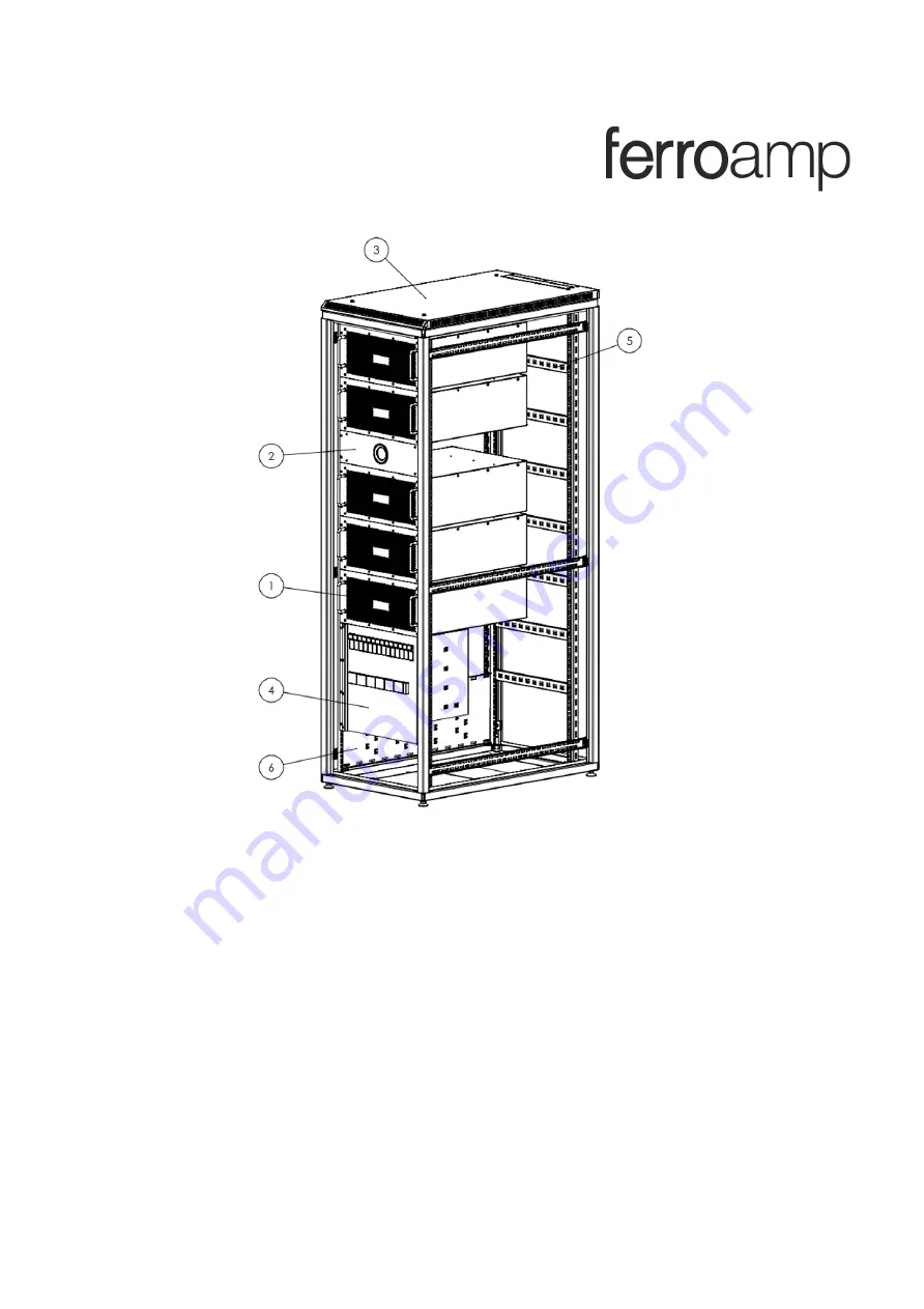
Page 10: ...designed for three EnergyHub XL The number may vary depending on how many inverters are connected to the cabinet 1 Terminals for AC connection 2 Terminals for DC connection 3 Breaker and fuses for AC 4 Fuses for DC to each EnergyHub Xl 5 Terminals for current transformers ...
Page 11: ...8 4 Internet Connection The System needs access to internet in order to present measurements and data to the portal as wells as software updates ...
Page 12: ...lay until it says Service menu activated Sweep right and left to switch between different views Sweep until you find the Table view seen below and verify that the system is inactive If not sweep to the Start and Stop menu and press Stop Go the CT ration view and insert the correct CT ratio To change the CT ratio push on the number ...
Page 13: ...to 5 minutes during this time a progress bar is displayed If the configuration fails check that the current transformers are correctly installed Om displayen visar Konfigureringen misslyckades är strömtängerna in rätt inkopplade Note in order to have a fully functional system the CT configuration must pass ...
Page 14: ...11 6 Single line diagram ...
Page 15: ...d the display until Service menu enabled is shown Choose ACE PV from the drop down menu Press the number at the bottom in order to change the threshold for the current equalization Press start Verify that the system is running the correct settings in the table view ...
Page 16: ...y until Service menu activated is shown Press Stop Press the number at the bottom in order to change the threshold for the current equalization Press Start Verify the status in the table view Press and hold the display to go back to operational mode ...
Page 17: ...urrent and Load current Grid current shows the current over the main fuse Load current shows the current inside the facility When ACE is activated the transferred currents is shown by the arrows between the phases ...
Page 18: ...nu enabled is shown Swipe to the Start and Stop display Choose ACE only in the drop down menu Choose the current limit that triggers the ACE function Press Start Verify the status at the table view Press and hold the display to go back to operational mode ...
Page 19: ...n Press and hold until Service menu enabled is shown Swipe to the start and stop display Choose PV only in the drop down menu Press Start Verify the status at the table view Press and hold the display to go back to operational mode ...