EN
5
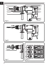
each machine function is given in the diagram
(Fig.C) on page 2.
1 = Demolition hammer/chisel
2 = Rotary hammer drill
3 = Drilling
Switching On/Off
• To start the drill, squeeze the trigger.
• To stop the drill, release the trigger.
Installing dust catcher
Fig. C
The dust catcher prevents large amounts of
drilling dust entering the machine when drilling
into ceilings:
• Remove the drill bit.
• Slide the dust catcher over the shaft of the drill
bit.
• Place the drill bit with catcher in the drill
chuck.
• Always replace a damaged dust catcher
immediately.
4. Maintenance
Take care that the machine is not
connected to power whenever
maintenance work on the mechanical
parts is taking place.
The machines are designed to function
problem-free for a long period with a minimum
of maintenance. Through regular cleaning and
correct treatment, you help assure a long working
life for your machine.
Defects
The machine should be regularly inspected for
the following possible defects, and repaired if
necessary.
• Damage to power cord
• Broken on/off trigger assembly.
• Short circuiting.
• Damaged moving parts.
Trouble shooting
1. When switched on, the motor does not
turn.
• Failure in power supply.
• Check the power supply.
• Poor contact in the on/off trigger.
• Repair or replace the trigger assembly.
• Mains voltage too low.
• Extension lead too long, or too light.
• Damaged motor.
• Have your machine repaired by an expert.
• Carbon brushes worn.
• Replace the carbon brushes
2. Motor generates excessive noise, and
runs too slowly or not at all.
• Motor is overloaded due to excessive
pressure or drilling depth.
• Reduce the pressure or drilling depth,
reduce power.
• Damaged motor.
• Have your machine repaired by an expert.
• Supply voltage too low.
• Adjust the supply voltage.
• Carbon brushes worn.
• Replace the carbon brushes
3. Overheating in the transmission case.
• Overloading of machine, or blunt drill bit
• Reduce the loading, or hone the drill bit.
Replacing carbon brushes
• Regularly check the carbon brushes for wear
and defects.
• Replace both carbon brushes at the same
time.
• Always replace worn-out carbon brushes.
• Always keep the carbon brushes clean, and
make sure that neither brush is obstructed.
• Open the machine to inspect/replace the
carbon brushes.
• Remove and replace the carbon brushes if
necessary.
Cleaning
Clean the machine casings regularly with a soft
cloth, preferably after each use. Make sure that
the ventilation openings are free of dust and
dirt. Remove very persistent dirt using a soft
cloth moistened with soapsuds. Do not use any
solvents such as gasoline, alcohol, ammonia,
etc. Chemicals such as these will damage the
synthetic components.
Lubrication
Fig. A
• Regularly grease the hammer drill shaft.
• Regularly check the grease-level inside the
machine:
• Remove the grease cap (12) on top of the
Summary of Contents for FBH-850KN2
Page 88: ...RU 88 O II 1 5 2 3...
Page 89: ...RU 89 360 11 O O D C 2 1 O 2 3 C 4 O 1 O...
Page 90: ...RU 90 O 2 O O 3 O A 12 4 2012 19 U...
Page 91: ...UK 91 2 FBH 850KN i SDS 1 2 3 4 i...
Page 93: ...UK 93 1 5 2 i 3 i 360 i i A i 11 i D 2 1 2 3 C 4 i...
Page 94: ...UK 94 i i 1 2 i i 3 i A 12 4 i...
Page 95: ...EL 95 i 2012 19 EU i Ferm Ferm 2 FBH 850KN SDS 1 2 3 4...
Page 97: ...EL 97 1 5 mm2 3 360 A B 11 C 2 1 2 3 D...
Page 98: ...EL 98 4 1 2 3...
Page 99: ...EL 99 A 12 4 2012 19 EU...
Page 101: ...BG 101 2 3 4 5 6 7 8 9 10 11 12 2...
Page 102: ...BG 102 1 5 mm2 3 3600 11 D 2 1 2 3...
Page 103: ...BG 103 4 1 2 3 Fig A...
Page 104: ...BG 104 12 4 2012 19 EU...
Page 107: ...Exploded view 107...
Page 108: ...www ferm com 2014 Ferm B V 1412 03...


