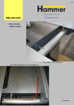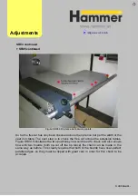
If the 90° angle that the shaper makes to the cast iron table (in the tilting plane only)
is not aligned to within the specified tolerance limits, then an adjustment can be made
to the 90° stop on the tilt-controlling axle. It is pictured in figure SH02.1 and can be
accessed through the cutout or from the access hatch for the shaper. You will need
to loosen off the stop with an allen screw first, turn it along the axle in the required
direction, lock it back into place and then return the shaper back to 90° to check the
new alignment. Once checked, re-adjust as necessary.
Figure SH02.1 The 90° stop on the tilt-controlling axle
Adjust
ments
S
H02 Shaper Spindle at 90° (for tilting spindles)
Summary of Contents for Hammer
Page 1: ...Machine Setup Guide InstallVersion1 09...
Page 5: ...15 Completion You re Good To Go 16 FAQ s 17 Links Contact Details Contents 3...
Page 32: ...The rip fence side is complete 11 Assembly...
Page 74: ...Figure SS03 2 End position 2 Adjustments Alignme nt Link SS03 continued...
Page 79: ...Figure SS07 3 Crosscut stop and block adjustment Adjustments Alignme nt Link SS07 continued...


