SR04 Rip Fence Free-cut at 90°
And SR05 Rip Fence Free-cut across all tables
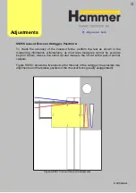
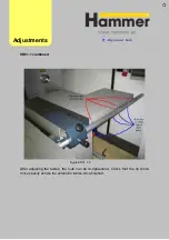
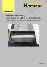
Figure SR04.1
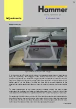
Once zero’d, slide the dial indicator to position 2, as shown in figure SR04.1. Again,
spin the saw blade through several revolutions in order to find the same low point,
where the saw blade is again closest to the rip fence. Note this value.
Point 2 should be further away from the saw blade than point 1, by the specified
tolerance.
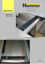
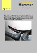
If it is not within tolerance there are adjustments available at the positions shown in
figure SR04.2. Figure SR04.3 illustrates how adjusting the rip fence bar will affect the
freecut.
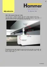
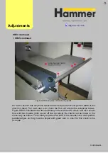
When making adjustments here, first loosen off the outer bolts, shown in figure
SR04.4 and then adjust the rip fence bar. After checking the free cut again, these
bolts can be re-tightened.
Adjust
ments
The best way to check the free cut of the
saw blade at 90° is to do it with a dial
indicator. You will also need a Ø300mm
saw blade.
Turn the machine off for this exercise as it
involves handling the saw blade.
Set the dial indicator up in position 1 as
shown in figure SR04.1
First, we must remove any error in the
calculation brought about by the tolerance
of the saw blade. In position 1, very
carefully spin the saw blade through
several revolutions and zero the dial
indicator on the lowest value (the closest
point on the saw blade to the rip fence).
Check the new zero before moving on.
Continued…
Summary of Contents for Hammer
Page 1: ...Machine Setup Guide InstallVersion1 09...
Page 5: ...15 Completion You re Good To Go 16 FAQ s 17 Links Contact Details Contents 3...
Page 32: ...The rip fence side is complete 11 Assembly...
Page 74: ...Figure SS03 2 End position 2 Adjustments Alignme nt Link SS03 continued...
Page 79: ...Figure SS07 3 Crosscut stop and block adjustment Adjustments Alignme nt Link SS07 continued...


