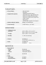
Identification
Installation
ID ISC.MR102
FEIG ELECTRONIC GmbH
Page 10 of 26
M01210-6e-ID.doc
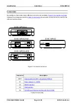
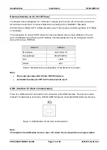
Antenna terminal ANT 1
A SMA socket is provided on the circuit board for connecting the external antenna.
The maximum tightening torque for the SMA socket is 0.45 Nm.
Caution:
Higher tightening torque will damage the connector.
Terminal
Description
X4
Connecting the external antenna
(input impedance 50
)
Table 3: Connecting the external antenna
Note:
The input impedance for the antenna must be calibrated to a value of
50
(15
15°).
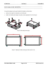
If the antenna ID ISC.ANT340240 is used a minimum distance of 20cm to any metal parts
are necessary. Otherwise there is a danger that the reader will be destroyed.
The optimum operating Q factor of the antenna should be in a range of QB = 10...20. To
determine the operating Q the antenna must be supplied with a 50 Ohm source such as
a network analyzer or frequency generator.
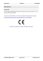
When connecting an antenna, ensure that it does not exceed the permissible limits pre-
scribed by the national regulations for radio frequency devices.
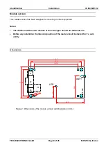
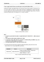
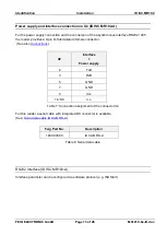
DC Voltage supply on antenna connector ANT1
The reader is able to provide a DC voltage on the antenna output ANT1. With this DC voltage a
external LED can be supported for example.
Note:
This DC voltage (7,5V± 1V) is designed for low current (max. 5mA) only.
Only antennas can be used which are designed for DC voltage and do not short cut DC
voltages.
For the connection of other devices (e.g. VSWR-Meter) it is necessary to check if DC
voltage is allowed.
This DC voltage is not sufficient for powering the ID ISC.DAT tuning board.