INSTALLATION
final
– public (B)
2017-03-30
– M70210-0e-ID-B.docx
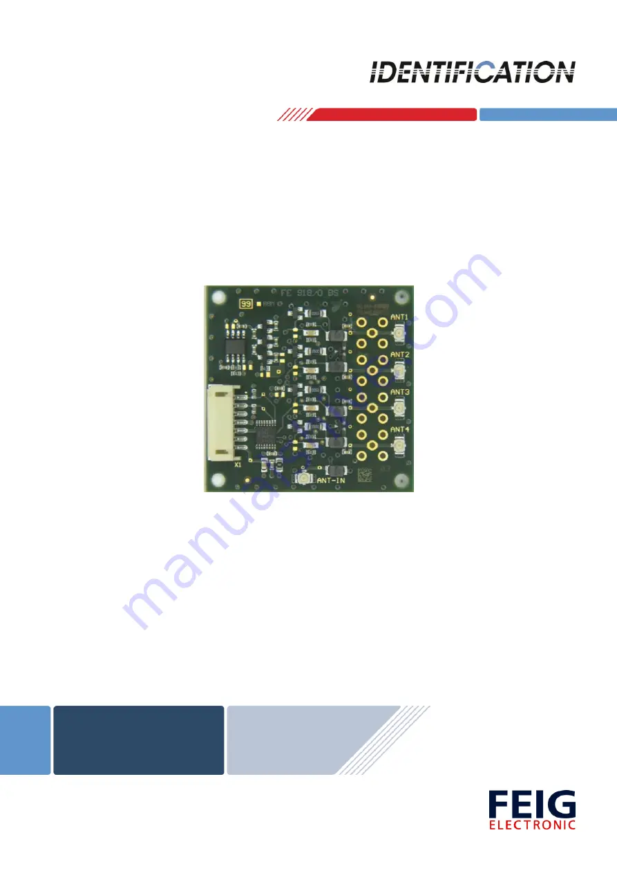
ID CPR.ANT.MUX.M4
(4775.000.00)
Antenna Multiplexer for Reader ID CPR74
Page 1: ...INSTALLATION final public B 2017 03 30 M70210 0e ID B docx ID CPR ANT MUX M4 4775 000 00 Antenna Multiplexer for Reader ID CPR74...
Page 2: ...s errors may not be completely avoided we are always grateful for your useful tips The instructions given in this manual are based on advantageous boundary conditions FEIG ELECTRONIC GmbH does not giv...
Page 3: ...ore start up 4 2 Performance Features of ID CPR ANT MUX M4 5 2 1 Scope of Delivery 5 2 2 Available Accessories and Spare Parts 5 2 3 References 5 3 Dimensions 6 4 Terminals 7 4 1 Terminal X1 7 4 2 Wir...
Page 4: ...zed measures shall exclude any liability by the manufacturer The liability prescriptions of the manufacturer in the issue valid at the time of purchase are valid for the device The manufacturer shall...
Page 5: ...ID CPR ANT MUX M4 2 2 Available Accessories and Spare Parts Table 1 Available accessories and spare parts Part No Name Description 3673 000 00 ID ISC ANT100 100 U FL A HF module antenna 100 mm x 100 m...
Page 6: ...C GmbH Page 6 of 14 M70210 0e ID B docx 3 Dimensions The antenna multiplexer ID CPR ANT MUX M4 is designed as electronic module and can be adapted on top of the ID CPR74 reader by using distance bolt...
Page 7: ...onnector X1 The following figure 4 and the corresponding table 2 show the pin assignment of the con nector X1 7 pole of type JST PH spacing 2 mm horizontal X1 Pin No Abbreviation Name 1 IN 1 Digital I...
Page 8: ...t not exceed 3 m to reduce the influence of noise Connection cables 0 5 m should be twisted paired and shielded Hf connection cables U FL 0 5 m should be wrapped around the connection cable to avoid g...
Page 9: ...ction overview to a reader ID CPR74 and figure 6 a sample of the con nection cable between the multiplexer and the Reader Figure 5 Connection overview Figure 6 Connection cable between the ID CPR ANT...
Page 10: ...G ELECTRONIC GmbH Page 10 of 14 M70210 0e ID B docx 4 3 Reader connection ANT IN The antenna output of the reader will be connected with the input ANT IN of the multiplexer by using a short U FL cable...
Page 11: ...hed external antennas The permanent usage of unmatched antennas can damage the connected reader electronic The antenna output is neither permanent short circuit protected nor permanent no load protect...
Page 12: ...NT MUX M4 FEIG ELECTRONIC GmbH Page 12 of 14 M70210 0e ID B docx 5 Indicators LED Each antenna output has a LED which shows the active antenna output channel Only one channel will be active at the sam...
Page 13: ...F Humidity max 95 not condensing MTBF 500 000 h Power Supply 5 V DC 5 Ripple 0 250 kHz 10 mVpp from 250 kHz 0 1 mVpp Current Consumption 40 mA I O Digital Input Low Pegel 0 1 0V High Pegel 3 8V VCC Pu...
Page 14: ...TRONIC GmbH declares that the radio equipment type ID CPR ANT MUX M4 is in compliance with Directive 2014 53 EU The full text of the EU declaration of conformity is available at the following internet...