Stages:
Software Stage Functions
7-9
•
Clicking the
Remove selected position
item deletes the selected
location(s) from the map and from the Location list.
The
Coordinates
tab /
Remove
button has the same functionality.
•
Clicking the
Magnification
item provides menu allowing the
Map
area magnification factor (
5
) to be selected. Scroll bars (
4
) appear
if necessary to move over the whole Map area.
•
The
Center view
item brings the selected location to the center of view.
•
When the
Auto center on target
item is ticked and the
Magnification factor is used, the active location remains in the
center of view.
•
The
Zero radar view
item resets the stage rotation to 0°, which is
represented by the black triangle 12 o’clock position.
•
The
Stage location overlay
item toggles the detector and
chamber door position display in relationship to a sample.
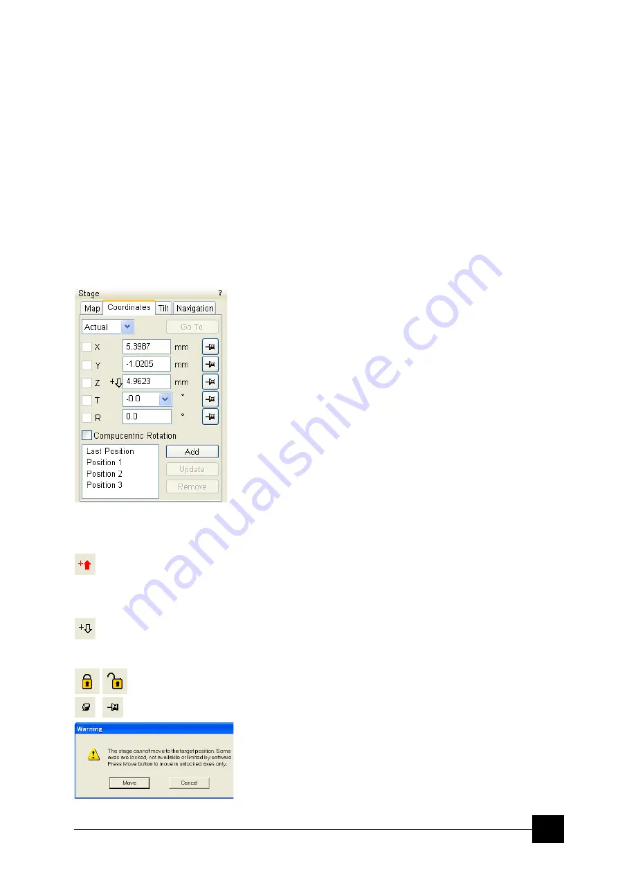
COORDINATES TAB
Three modes are possible via the list box:
•
The
Actual
mode
(default) displays actual position coordinates in
the edit boxes.
•
The
Target
mode
activates when clicking a stored position or when
editing a coordinate value.
•
The
Relative
mode
is used to move stage by a given value and to
repeat it several times if needed.
Clicking the
Go To
button drives the stage to a new location. This only
acts on just edited coordinates (with a tick mark). Pressing the Enter
key after editing of any coordinate value works as the Go To button
short-cut. Double-clicking a stored location moves the stage to the
desired position immediately.
During the stage motion the
Go To
button changes to the
Stop
button,
which stops the stage immediately.
Coordinates X, Y, Z, R, T
Edit boxes for
X, Y, Z, R
and
T
coordinates are filled with the selected
or actual position values. The value changed is automatically ticked.
C a u t i o n !
•
Danger of hitting the pole piece! The
Link Z to FWD
procedure did
not pass (see Chapter 4). The red arrow next the Z axis alerts the
positive Z-axis stage moving direction is up. It means raising a
value in the Z axis edit box causes moving the stage up towards
the pole piece.
•
After running the
Link Z to FWD
procedure the symbol and the
stage moving direction changes. The black arrow next the Z axis
indicates the positive Z-axis stage moving direction is down.
The
units of measure follow the
Preferences…
/
Units
setting, unless
the
Stage
menu /
User Units
function is active, in which case UU is
displayed for X and Y.
The software
locks
prevent inadvertent stage movement of selected
axes during particular applications. The edit boxes for locked axes are
disabled and the stage does not move in these directions. When any
or all axes are locked the
Status
module displays a closed lock
instead of an open one. By default all axes are unlocked.
When any axis is locked and the stage movement is required in that direction
(trying to move to the stored position), the warning dialogue appears.
Summary of Contents for Quanta FEG 250
Page 8: ...C vi...
Page 28: ...System Operation Quanta FEG System States 3 10...
Page 108: ...Alignments 1 Gun Alignment 6 6...
Page 114: ...Alignments 154 Water Bottle Venting 6 12 154 Water Bottle Venting...
Page 152: ...System Options Automatic Aperture System 9 4...
Page 154: ...System Options Nav Cam 9 6 401 NAV CAM AUTOBRIGHTNESS...
Page 177: ...System Options Cooling Stage Waterless Cooling Stage 9 29...


