background image

Page 7 of 40 

(4)


GENERAL ELECTRICAL & GROUNDING


DANGER: 

Improper or faulty hookup of electrical components in the display case can result 
in severe injury or death. 

4.1


CORD CONNECTED 

All standard models are supplied with a power cord that is properly sized to the amperage 
requirements of the case. See the electrical data plate located on the rear left interior of the case for 
the proper circuit size for each case. 
The cord is factory installed protruding from the bottom rear corner of the case. 
A separate circuit for each display case is required to prevent other appliances on the same circuit from 
overloading the circuit and causing malfunction. 

4.2


PERMANENT CONNECTED (OPTION) 

Only a licensed electrician must perform all case electrical connections.


All electrical wiring hookups must be done in accordance with all applicable local, regional, or national 
electrical standards. 
A separate circuit for each display case is required to prevent other appliances on the same circuit from 
overloading the circuit and causing malfunction. 
The electrical service must be grounded upon installation. 
See the electrical data plate located at the rear of the case for proper circuit size and wire ampacity. 
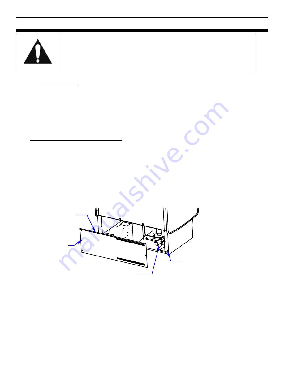
The electrical connection box is accessible from the rear of the case with rear grill removed. 

FIELD CONNECTION BOX

POWER CORD OR
CONDUIT CONNECTION
HOLE (7/8"

O

)

REAR BASE 
PANEL

(6) REAR BASE 
PANEL SCREWS


Summary of Contents for LPRSS Series

Page 1: ...3 Rev A 09 01 2018 Installation Operation Instructions Refrigerated LPRSS ELPRSS Models Federal Industries 215 Federal AVE Belleville WI 53508 Toll Free 800 356 4206 WI Phone 608 424 3331 Fax 608 424...

Page 2: ...5 6 Evaporator Condensate Drain Tube 10 5 7 Condensate Pump 11 6 Shelving Installation Removal 13 6 1 Metal Shelves 13 6 2 Glass Shelves 14 6 3 Optional Shelf Lights ELPRSS 15 7 Plastic End Removal In...

Page 3: ...structions 33 16 3 Refrigeration Electrical Data 33 16 4 Electronic Control Operation 33 16 4 1 Operation 33 16 4 2 Defrost Cycle 34 16 5 Control Parameters 34 16 6 Error Codes 34 16 7 Refrigeration O...

Page 4: ...ponents contain technical instructions intended only for persons qualified to perform electrical work DANGER Improper or faulty hookup of electrical components in the case can result in severe injury...

Page 5: ...owing signal words are used in the warning and safety messages DANGER Severe injury or death will occur if you ignore the message WARNING Severe injury or death can occur if you ignore the message CAU...

Page 6: ...oted to shipping crates cartons or if a shortage is found note this on the bill of lading all copies prior to signing If damage is discovered when the case is uncrated immediately call the delivering...

Page 7: ...om overloading the circuit and causing malfunction 4 2 PERMANENT CONNECTED OPTION Only a licensed electrician must perform all case electrical connections All electrical wiring hookups must be done in...

Page 8: ...or damaged items as explained in the pre installation procedures outlined above 2 Move the case as near as possible to the final location and before removing it from the shipping skid 3 Remove the 4...

Page 9: ...ble and the gap between the cases must be tight and even If the gap is larger at the top or the bottom adjust leg levelers accordingly HOLD CASES TOGETHER AS TIGHT AS POSSIBLE WHILE ATTACHING ALL JOIN...

Page 10: ...aporator coil expansion valve sight glass service valves and refrigerant solenoid valve Installation must be performed by a licensed Refrigeration Technician See the Service section of this manual for...

Page 11: ...Optional on all models Installer must check unit to see if a condensate pump has been provided with case WARNING TO INSTALLER Installer must determine if case was provided with condensate pump Failur...

Page 12: ...ovided in the base as noted in the drawing above Plugs or caps will need to be removed in the desired exit location The hose can be run the entire 50ft in any direction as required but no higher than...

Page 13: ...SHELF BRACKET SHELF STANDARD 1 Place shelf bracket top hook into desired shelf standard slot 2 Lift shelf bracket top hook to allow shelf bracket bottom tab to clear shelf standard slot 3 Swing shelf...

Page 14: ...TO GLASS BOTTOM TOP VIEW CLEAR PRODUCT STOP CLEAR PRODUCT STOP CLEAR PRODUCT STOP FIELD INSTALLED TO GLASS FRONT LIP GLASS SHELF RETAINER CLIP 1 When installing for the first time attach 2 glass shelf...

Page 15: ...lights a shelf support will be placed on the back and front of the shelf bracket 2 Remove the cap from the appropriate female light sockets 3 Plug in each shelf light by plugging the male plug on the...

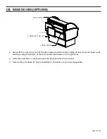
Page 16: ...when moving or installing case and can easily be reinstalled REMOVAL 1 Lift the back side of the panel out to disengage 2 Velcro style pads 2 Slide the panel forward to disengage the 4 Key slots in p...

Page 17: ...oor and lift the door upward until the bottom edge of door clears the lower track and then swing the bottom of the door outward and down out of upper track 2 After the outer door is removed repeat the...

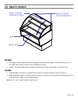
Page 18: ...ss the top of case and down the front 2 Attach the snap located under the night curtain strap on to the snap located on the front trim CLOSING 1 Grab the night curtain strap and detach the snap from t...

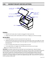
Page 19: ...of the front trim 3 Set the top flange of the security cover down against the top panel 4 Turn the lock handle so it engages the lock handle catch and use key to lock it in place Note The 6 models ha...

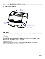
Page 20: ...the lights This switch is located behind a lift up panel on the unit base Light Switch The unit has a light switch that turns on and off the interior lights of unit The switch is located inside the d...

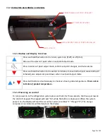
Page 21: ...his button for 3 seconds to initiate a manual defrost and cancel defrost if initiated also adjusts set point down when in set point adjust mode Press both buttons simultaneously to check air stream pr...

Page 22: ...e a manual defrost press and hold the red down arrow for 3s The control will read dEF while the button is being held The defrost is initiated when the orange snowflake appears on the control display 1...

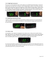
Page 23: ...as described above in 11 2 2 At start up from a warm unit it is recommended that the temperature control is set to a warmer setting such as 1 After the unit has gone through several cycles adjust the...

Page 24: ...45kg 250lbs 114kg E LPRSS4 100lbs 45kg 135lbs 61kg 320lbs 146kg E LPRSS5 120lbs 55kg 170lbs 77kg 390lbs 177kg E LPRSS6 150lbs 68kg 210lbs 95kg 460lbs 209kg Determine desired shelving location before...

Page 25: ...g and can become dislodged in shipment To ensure proper airflow and performance of the case make sure that the display deck is pushed completely down Allow refrigerated models to run for at least two...

Page 26: ...the body under the locking tab on plastic clip Re install cord plug SHELF LIGHTS Unplug cord from light Use putty knife to pry LED light body from Shelf and or Top Light Liner It may be useful to slid...

Page 27: ...condenser warranty 1 Disconnect power to the unit 2 Remove the front panel located on the front bottom of unit by removing the 4 front panel retaining screws 3 Carefully vacuum the front surface of c...

Page 28: ...is case is not designed to be cleaned by flushing Note For major spills or foreign material buildup perform the weekly cleaning instructions 1 If Supplied With Optional Rear Doors Clean all foreign ma...

Page 29: ...llation and Removal section of this manual Remove all interior shelving as described in the shelving installation and removal section of this manual 3 Remove both shelf standards from interior of case...

Page 30: ...led to allow proper cleaning of the unit 8 Clean all shelves shelf support bars shelf brackets and display pans using warm soapy water and a brush Rinse thoroughly and allow to dry 9 If supplied with...

Page 31: ...ntact the customer service department at Federal Industries at 800 356 4206 The customer service department at Federal Industries should be contacted at the time of sale or disposal of your case so re...

Page 32: ...call by first reviewing this checklist of frequently encountered situations that can cause unsatisfactory case performance CAUTION Before servicing case turn off power at the main breaker of fuse box...

Page 33: ...VOLTAGE AMPERAGE CORD STYLE LPRSS3 ELPRSS3 2 LBS 120 60 1 15 20AMP NEMA 5 20 120 60 1 3 15AMP NEMA 5 15 LPRSS4 ELPRSS4 3 LBS 120 60 1 15 20AMP NEMA 5 20 120 60 1 3 15AMP NEMA 5 15 LPRSS5 ELPRSS5 4 LBS...

Page 34: ...6 7 C or lower for five minutes Once initiated the defrost cycle will terminate when evaporator coil sensor reaches 45 F 7 2 C If a manual defrost is required one can be initiated by pressing and hold...

Page 35: ...Resistance Minimum Resistance 32 F 0 C 27 83 27 28 26 74 77 F 25 C 10 1 10 9 9 212 F 100 C 1 0 97 0 94 16 7 REFRIGERATION OPERATION 16 7 1 Self Contained Models The self contained models are shipped...

Page 36: ...lines should be pitched downward towards the condensing unit at least per 10 run to aid the oil drainage A P trap must be installed in the suction line at the foot of every riser to insure oil return...

Page 37: ...9 8 7 6 5 4 TEMP PROBE DEFROST RANCO BLU R R G G 17 2 REMOTE W COLOR CODE B BLUE Y YELLOW W WHITE R RED BLK BLACK BRW BROWN CORD PLUG W G 91 19494 REV B 06 05 18 CONDENSATE PUMP OR EVAPORATOR BLK EVA...

Page 38: ...re 5 13 72 11450 1 72 17987 2 72 11450 2 72 11450 2 Evaporator Fan Blade After 5 13 72 11450 1 72 11450 1 72 11450 2 72 11450 2 Latch Evaporator Housing to Coil 66 13640 Condnsate Pump Std 5 6 47 1568...

Page 39: ...ed SA4361 R Pad 1x1 End Panel Dual Lock 250 77 17849 Pad 1x1 Cabinet Dual Lock 170 77 17848 ELPRSS PANELS ELPRSS3 ELPRSS4 ELPRSS5 ELPRSS6 Acrylic End Clear 15 19808 LPRSS SHELVING LPRSS3 LPRSS4 LPRSS5...

Page 40: ...1 Security Night Cover Panel Optional M16107 1 M16107 2 M16107 3 M16107 4 Security Night Cover Latch Optional 66 11727 Night Curtain Black 65 19459 65 19460 65 19458 65 19300 Step Riser Top Optional S...

Reviews: