Installation, Maintenance,
and Service Manual
25500675
Rev. A0 1020
Printed in U.S.A.
© Copyright 2020 Federal Signal Corporation
Models SIFM,SIFZ (Discrete) and
Models SIFMJ, SIFZJ FSJoin
™
(Serial)
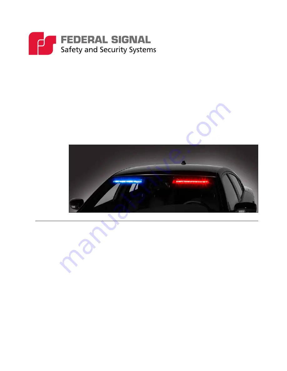
Front ILS Light Bar
Page 1: ...stallation Maintenance and Service Manual 25500675 Rev A0 1020 Printed in U S A Copyright 2020 Federal Signal Corporation Models SIFM SIFZ Discrete and Models SIFMJ SIFZJ FSJoin Serial Front ILS Light Bar ...
Page 2: ...ranty is in lieu of all other warranties express or implied con tractual or statutory including but not limited to the warranty of merchantability warranty of fitness for a particular purpose and any warranty against failure of its essential purpose blank page 2645 Federal Signal Drive University Park Illinois 60484 3167 www fedsig com Customer Support Police Fire EMS 800 264 3578 1 708 534 3400 W...
Page 3: ... ILS in the Vehicle 14 Maintaining the SIF ILS 16 Cleaning the Shrouds 16 Cleaning the Reflectors 16 Servicing the SIF ILS 17 Replacing a PCB 17 Getting Technical Support and Service 19 Getting Repair Service 19 Ordering Replacement Parts 20 Figures Figure 1 DIP switch locations the control boards of the serial controlled ILS SIFM shown 10 Figure 2 Discrete wire control cable on the pasenger side ...
Page 4: ...he serial controlled ILS 10 Table 2 SIFM Rear light bar controls and wires from the Serial Interface Module 11 Table 3 Description of SIF SpectraLux ILS control wires 12 Table 4 Discrete wire SIF light bar controls 13 Table 5 Replacement parts for Rear SIFM light bar Figures 4 and 5 20 Table 6 Replacement parts for Split SIF ILS light bar Figures 6 and 7 22 ...
Page 5: ...ower supplies and light heads are designed to work together as a system Combining light heads and a power supply from different manufacturers may reduce the warning effectiveness of the lighting system and may damage the components Verify or test your combination to ensure that the system works together and meets federal state and local standards or guidelines Electrical Hazards Strobe systems pre...
Page 6: ...ou have verified that no shorts exist If the wiring is shorted to the vehicle body or frame high current conductors can cause hazardous sparks resulting in electrical fires or flying molten metal DO NOT install equipment or route wiring or the plug in cord in the deployment path of an airbag Before mounting any components check the manual to enure that the component you are installing is suitable ...
Page 7: ... safe place and refer to them when maintaining and or reinstalling the product Failure to follow all safety precautions and instructions may result in property damage serious injury or death RETAIN AND REFER TO THIS MESSAGE Safety Message to Operators of Warning Light Equipment People s lives depend on your safe use of our products Listed below are some important safety instructions and precaution...
Page 8: ...e nearest service center At the start of your shift ensure that the entire warning light system and the siren system are securely attached and operating properly Suction cup mounting is for temporary applications only The unit should be removed from the window and stored securely when not in use Temperature changes and sunlight can cause suction cups to lose holding power Periodically check the un...
Page 9: ...the user supplied low current switches Serial models are controlled through the CAT5 serial communication cable The cable connects to Federal Signal Convergence network controllers or the Convergence Serial Interface Module Part Number 858303641 With the Serial Interface Module the lightbar can be activated by Federal Signal lightbar controllers or individual low current switches The backbone is a...
Page 10: ...rial controlled ILS SIFM shown Table 1 Switch settings on the control board of the serial controlled ILS DIP Switch Position Function 1 Not used 2 Not used 3 Activating a Front or Rear Mounted SIFM To activate a front mounted SIFM set Switch 3 OFF To activate a rear mounted SIFM set Switch 3 ON 4 Sets the ability to power the network cable for other devices The default is OFF Switch 4 should only ...
Page 11: ...driver side or two heads driver and passenger side burn steadily when 12 Vdc is applied to the control wire for Steady Burn Front Cutoff Green White Turns OFF power to the Split Front ILS Front Enable Turns ON power to the Split Front ILS Rear Cutoff Orange Black N A Rear Enable N A Scene Light Left Blue Black Applying 12 Vdc to the Scene Light Left wire turns on the left half of the light bar Fla...
Page 12: ...ode 1 Takedowns Black Applying 12 Vdc provides white light to the front Overrides flashing lights White Flashing Light Blue When calling for the right of way a vehicle responding to an emergency is permitted to have white light Applying 12 Vdc activates the white flashing LED heads Dimming Light Brown Applying 12 Vdc dims the light bar 50 percent Steady Burn Red Red One driver side or two red LED ...
Page 13: ...etting let the function run for five seconds before removing power The available programming functions are listed in Table 4 Table 4 Discrete wire SIF light bar controls Light Bar Programming Wire Color Programming Functions Mode 1 Flash Orange 28 flash patterns four cruise patterns Mode 2 flash pattern overrides Mode 1 Mode 2 Flash Yellow 28 flash patterns dimming disabled Takedowns Black Takedow...
Page 14: ...tallation check the entire system to be sure the lights flash properly and all light system functions operate properly Wiring the SIF ILS in the Vehicle INSTALLATION PRECAUTIONS The warning system and or two way radio system may operate improperly if a two way radio antenna is installed on or within 18 inches of the light bar Before permanently installing the light bar or a two way radio antenna t...
Page 15: ...are adequately fused From the light bar route the CAT5 control cable into the vehicle cab or trunk near the planned location of a control head that is compatible with the light bar or Serial Interface Module 2 Connect the 16 AWG black lead to the battery ground NEG terminal 3 Connect the 16 AWG red lead through the supplied 15 A fuse at the source to the positive BAT terminal ...
Page 16: ...and water but take care not to get water on the PCBs 3 When finished make sure the light bar is completely dry before reinstalling it according the vehicle specific installation instructions Cleaning the Reflectors CRAZING HAZARD Crazed cracked or faded domes or reflectors reduce the light output and the effectiveness of the lighting system Tops or reflectors showing this type of aging must be rep...
Page 17: ... page 10 for the DIP switch setting For the discrete wire model see Programming the Discrete Wire SIF ILS on page 13 for information on cycling through the flash patterns using the white programming wire To replace a PCB 1 Remove the light bar from the vehicle according to the vehicle specific installation instructions included with the SIF ILS 2 See Figure 3 on page 18 Remove the 10 screws that h...
Page 18: ...LS Light Bar Federal Signal www fedsig com Servicing the SIF ILS Figure 3 Exploded view of passenger side SIF ILS vehicle specific POWER GROUND CONNECTOR TO REMOVE WIRES PRESS THE TABS 6 32 NUTS CABLE CLAMP NYLON SPACER 10 SCREW GROMMET SOME VEHICLES REFLECTOR ...
Page 19: ... Federal Signal factory provides technical assistance with any problems that cannot be handled locally Any units returned to Federal Signal for service inspection or repair must be accompanied by a Return Material Authorization RMA Obtain a RMA from a local Distributor or Manufacturer s Representative Provide a brief explanation of the service requested or the nature of the malfunction Address all...
Page 20: ...sembly configured 3 8 77700356 Nylon Spacer 4 1 Contact Service Driver Side PCB Assembly configured 5 1 Contact Service Passenger Side PCB Assembly configured 6 8 862400828 ZILS Wide Reflector 7 8 7058A035 6 32 Steel KEPS Nut 8 1 17500009 36 SILS Board to Board Cable 9 2 8240A072 1 4 inch Nylon Clamp 10 1 1751357 02 25 foot CAT5 Cable Serial 1 17500274 300 SIF ILS Cable Discrete 11 1 C300216 02 07...
Page 21: ...21 Installation Maintenance and Service Manual Federal Signal www fedsig com Ordering Replacement Parts Figure 5 Exploded view of Split SIF ILS SIFM shown 19 16 3 1 4 13 17 2 5 6 7 18 14 9 14 15 ...
Page 22: ... 6 32 Steel KEPS Nut 10 1 1751357 02 25 foot CAT5 Cable Serial 1 17500274 300 SIF ILS Cable Discrete 11 1 C300216 02 079 180 inch C Wire 3 8 inch NT 3 8 inch NT 12 1 C300216 10 102 180 inch C Wire 3 8 inch NT 3 8 inch NT 13 1 77700488 5 16 inch Nylon Clamp 16 1 8624xxxxx Passenger Side Upper Shroud configured 17 2 7011246 06 10 Type B Black 6 Lobe Screw 18 2 1612358 Eye Damage Warning Label 19 1 8...
Page 23: ...23 Installation Maintenance and Service Manual Federal Signal www fedsig com Ordering Replacement Parts Figure 7 Exploded view of Split SIF ILS passenger side 18 19 16 17 13 7 6 5 3 20 2 ...
Page 24: ...al Signal Drive University Park Illinois 60484 3167 www fedsig com Customer Support Police Fire EMS 800 264 3578 1 708 534 3400 Work Truck 800 824 0254 1 708 534 3400 Technical Support 800 433 9132 1 708 534 3400 ...