background image

Description, Specifications, Installation, 

Operation, and Service Manual 

25500538

Rev. C1 1220

Printed in U.S.A.

© Copyright 2019-2020 Federal Signal Corporation
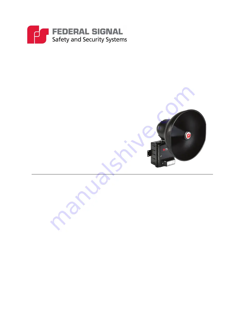
Informer15 Speaker 

Model I-IP15X Series C

IP-Enabled Indoor/Outdoor Speaker

For use in hazardous locations

Summary of Contents for I-IP15X Series

Page 1: ...stallation Operation and Service Manual 25500538 Rev C1 1220 Printed in U S A Copyright 2019 2020 Federal Signal Corporation Informer15 Speaker Model I IP15X Series C IP Enabled Indoor Outdoor Speaker For use in hazardous locations ...

Page 2: ...call 1 708 534 3400 This limited warranty is in lieu of all other warranties express or implied contractual or statutory including but not limited to the warranty of merchantability warranty of fitness for a particular purpose and any warranty against failure of its essential purpose 2645 Federal Signal Drive University Park Illinois 60484 www fedsig com Customer Support 800 548 7229 1 708 534 340...

Page 3: ...ecifications 10 Installation 13 Flat Surface Mounting 14 Opening the Housing 15 Wiring the Network and Power Connections 15 PoE model See Figure 2 15 24 Vdc model See Figure 3 16 Wiring to the Controller Board 16 Closing the Housing 18 Testing 18 Maintenance 18 Ordering Replacement Parts 19 Getting Service 19 Figures Figure 1 Depth and Height of Informer15 Speaker 14 Figure 2 I IP15 PC Boards 15 F...

Page 4: ... Connectors and Jacks for the Controller Board 11 Table 5 Connectors and Jacks for the Amplifier Board 11 Table 6 Connectors and Jacks for the PoE Board PoE models only 12 Table 7 Connectors for the 24 Vdc Power Board 12 Table 8 Visual Indications for the Controller Board 12 Table 9 Visual Indications for Amplifier Board 12 Table 10 Environmental and Physical 12 Table 11 Replacement Parts 19 ...

Page 5: ...Activating the Informer15 Speaker may not result in people taking the desired actions if those to be warned are not properly trained about the meaning of warning sounds Users should follow FEMA recommendations and instruct those to be warned of correct actions to be taken After installation service or maintenance test the system to confirm that it is operating properly Test the system regularly to...

Page 6: ...vice Provider Never alter the unit in any manner The nameplate should NOT be obscured as it contains cautionary and or other information of importance to maintenance personnel After installation and completion of initial system test provide a copy of these instructions to all personnel responsible for operation periodic testing and equipment maintenance File these instructions in a safe place and ...

Page 7: ... run in conduit Ethernet wiring must be at least six feet from bare power wiring or lightning rods and associated wires and at least six inches from other wire for example antenna wires doorbell wires wires from transformers to neon signs steam or hot water pipes and heating ducts Do not place Ethernet wiring or connections in any conduit outlet or junction box containing high voltage electrical w...

Page 8: ... useful if the location has no network connectivity but where voice and tone alerts from locally activated inputs are required The Informer15 can be networked later and the activations can be brought into the Commander system for full system capability When the Informer15 is networked using the Commander software alerts initiated at the Informer15 can be used to activate other devices The Commande...

Page 9: ...e and noise level adjustments Speaker as a microphone for talk back feature Alerts can be sent to single devices groups or zones or all devices Integrated Modbus TCP industrial PLC interface for control and monitoring Integrated SIP phone interface for live PA remote wave file and function control Commander and CommanderOne HMI software provide configuration control activation and notification opt...

Page 10: ...dc model 24 Vdc 1 0 A Serial Port Protocol FLASH programming and configuration Default 9600 bit s 8 data 1 stop no parity Configurable up to 115 200 bit s Open Collector Output Maximum 30 V or 100 mA maximum speaker provides 24 Vdc 20 mA maximum for a suitably listed external relay Ethernet Port for PoE model IEEE 802 3 10 100 Base T connection with PoE 802 3at Type 2 25 5 W Ethernet Port for 24 V...

Page 11: ...nd 2 to restore to factory defaults JP6 Open Collector Output 1 Output 1 Open Collector Output 2 Output 1 24 Vdc JP8 Option1 Jumper Short pins 1 and 2 for Standalone Option JP9 Option2 Jumper Short pins 1 and 2 for Option JP11 Serial Port RJ25 6 conductor mod jack JP12 Controller to Amplifier Interface JP13 microSD FLASH card holder M1 Communications from PoE board Table 5 Connectors and Jacks for...

Page 12: ...ual Indications for the Controller Board D1 Power D2 Digital Input 1 active D3 Listen D4 Talk D5 Digital Input 2 active D7 Network connected D8 CPU running D9 Digital Input 3 active D11 Digital Input 4 active D19 Relay Output active Table 9 Visual Indications for Amplifier Board D6 Power LED D8 ARM LED Table 10 Environmental and Physical Operating temperature range 22 F to 149 F 30 C to 65 C Humid...

Page 13: ... national and local electrical codes acting under the direction of the installation crew safety foreman should perform the installation OBSTRUCTION HAZARD Property damage serious injury or death could occur if an accumulation of water snow dust etc resides in the speaker projector or if any objects are in front of the speaker severely reducing or preventing operation of this device Mount the unit ...

Page 14: ...the mounting surface See Figure 1 for mounting hole locations and dimensions DRILLING PRECAUTION Before drilling holes in any surface ensure that both sides of surface are clear of items that could be damaged 3 Secure the unit to a wooden mounting surface with 10 x 1 inch wood screws If mounting on a metal surface drill 13 64 inch diameter holes and secure the unit with 10 screws lock washers and ...

Page 15: ...s an eight pin Ethernet port for connecting to the network Ethernet wire runs must be less than 328 feet 100 meters from the nearest network switch Do not install in a conduit carrying high voltage The wired Ethernet port auto negotiates a 10 100 full or half duplex connection and provides PoE to the Informer15 Speaker Do not remove the prewired Ethernet cable between the PoE supply PCB J2 and the...

Page 16: ...oller Board 24 Vdc Power Input Board Amplifier Board To Amplifier Board To 24 Vdc Power Input Board JP1 JP2 JP3 M1 GND GND 24 Vdc 24 Vdc Wiring to the Controller Board To wire the Controller Board 1 Use JP13 to provide tone and messages into the Informer15 via the microSD memory card 2 If local activations are required use JP2 The Alarm Initiation Inputs are activated by shorting the input to the ...

Page 17: ...n of this manual When using this feature the open collector relay outputs turn on until one of the following occurs Until the programmed default timeout occurs Until the CANCEL or RESET command is received You can configure the open collector relay output to open close and cycle based on a pre programmed sequence The open collector relay output can also be configured to turn on when PA VOIP is act...

Page 18: ...l system test establish a program for periodic testing of this device 3 Provide a copy of these instructions for the Safety Engineer system operator s and maintenance personnel Safety Message to Operators Even if your warning system is operating properly it may not be completely effective People may not hear or heed your warning signal You must recognize this fact and ensure that your warning sign...

Page 19: ... refer to the Safety Message before proceeding EXPLOSION HAZARD Do not disconnect the equipment unless power has been switched off or unless the area is known to be non hazardous SOUND HAZARD Unauthorized repair servicing of the unit may result in degradation of performance and or safety resulting in property damage serious injury or death to you or others If a malfunctioning unit is encountered d...

Page 20: ...2645 Federal Signal Drive University Park Illinois 60484 3167 www fedsig com Customer Support 800 548 7229 1 708 534 3400 Technical Support 800 524 3021 1 708 534 3400 ...

Reviews: