FEDERAL SIGNAL CORPORATION
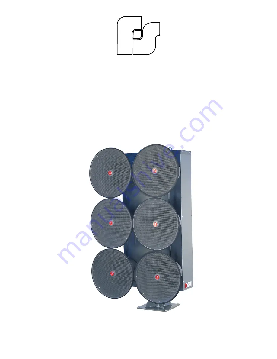
Model EOWS-612
Rotating Speaker Array
INSTALLATION INSTRUCTIONS
Page 1: ...FEDERAL SIGNAL CORPORATION Model EOWS 612 Rotating Speaker Array INSTALLATION INSTRUCTIONS ...
Page 2: ...nd such examination reveals a defect in material and or workmanship This warranty does not cover travel expenses the cost of specialized equipment for gaining access to the product or labor changes for removal and re installation of the product The Federal Signal Corporation warranty shall not apply to components or accessories that have a separate warranty by the original manufacturer such as but...
Page 3: ...erative that knowledgeable people who are provided with the necessary information are available at all times to authorize the activation of the sirens When sirens are used out of doors people indoors may not be able to hear the warning signals Separate warning devices or procedures may be needed to effectively warn people indoors The sound output of sirens is capable of causing permanent hearing d...
Page 4: ...ce test the siren system to confirm that it is operating properly Test the system regularly to confirm that it will be operational in an emergency If future service personnel do not have these warnings and all other instructions shipped with the equipment to refer to the siren system may not provide the intended audible warning and service personnel may be exposed to death permanent hearing loss o...
Page 5: ...ections in the interior of the Speaker Array A 3 foot 0 914m length of flexible conduit contains wires which are interconnected between the Speaker Array and a junction box In addition a 50 foot 15 2m length of multi conductor cable is connected to the junction box for connection to the Control Unit This instruction sheet is intended to be used in conjunction with the MCP Installation and Maintena...
Page 6: ...et to align the Speaker Array with an arrow on the Speaker Array base plate indicating Zone 1 Home or North If Home Switch Assembly adjustment is necessary it may be performed now or after Pole Mounting Figure 2 Motherboard Relay Connection Figure 3 Wooden Block Removal or Flat Surface Mounting is completed Refer to paragraph III D for a description of the adjustment procedure 5 Replace both panel...
Page 7: ...Use previously made wire tags step 2b or see figure 6 to ensure the proper connections 3 Ensure that the wooden blocks located near the rollers at the bottom of the rotator assembly have been removed as described in paragraph III A 2 WARNING The eyebolts and hoisting bracket do not have sufficient strength to support the combined weight of the Speaker Array and a utility pole Therefore do NOT atte...
Page 8: ...ductor cable from the junction box through conduit to the Control Unit Tighten the conduit connectors on the junction box and Control Unit 9 Secure the junction box to the pole with four 1 4 inch lag bolts not supplied C Flat Surface Mount WARNING The sound output of the Model EOWS 612 is capable of causing permanent hearing damage Therefore it is recommended that notices be posted at all roof acc...
Page 9: ...ne eyebolt The assembly is designed to be lifted by utilizing both eyebolts 2 Hoist the Speaker Array to the installation site using both eyebolts as lifting points 3 Anchor the Speaker Array to the mounting surface with user supplied 1 2 lag bolts or nuts and bolts as appropriate through the four inner and four outer mounting holes in the Speaker Array base plate NOTE When using the weight distri...
Page 10: ...viously removed screws Figure 10 Home Switch Adjustment E Signal Connections All interconnections between the Junction Box and the Control Unit are accomplished by means of a 50 foot length of multi conductor cable This cable is factory connected to the junction box A slip on terminal is factory installed on the free end of each color coded conductor in the cable NOTE Trim excess interconnecting c...
Page 11: ...7 Figure 11 EOWS 612 Wiring Diagram ...
Page 12: ...256622 REV F 6 03 Printed in U S A ...