Federal Signal Corporation CAMSET56-NTSC-2, Installation And Operation Manual
The Federal Signal Corporation CAMSET56-NTSC-2 is a high-quality surveillance camera system designed for optimal security. Ensure proper installation and operation of your device by downloading the free Installation And Operation Manual from our website. Stay informed and protect your property with this comprehensive manual.
Share
Download


Reviews:
No comments
Related manuals for CAMSET56-NTSC-2
T10
Brand: LAMAX Pages: 7

R50
Brand: Kaiser Baas Pages: 2
axis CC20 Series
Brand: Audioxtra Pages: 3
A800
Brand: 70mai Pages: 60

P3
Brand: Papago Pages: 82

Backup Camera
Brand: Yada Pages: 20

CH-300
Brand: CammSys Pages: 37
LT-510
Brand: LANCERTECH Pages: 9
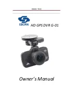
G-01
Brand: Eborn Pages: 20

Pinnacle
Brand: FalconEye Electronics Pages: 5
X23
Brand: G-Tech Pages: 14

Z9
Brand: Xblitz Pages: 64
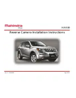
XUV500
Brand: Mahindra Pages: 12
MSR200
Brand: Navitel Pages: 15
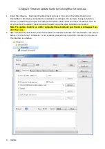
Z3
Brand: Z-EDGE Pages: 4

ADR-3000
Brand: T-Eye Pages: 23
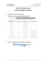
CDR-E07
Brand: Vacron Pages: 2
CDR-E07
Brand: Vacron Pages: 5


