PosiDRIVE Security Gate
ZMA-330, Ver. 6
Installing the Gate Arm •
35
4.
Manually raise the arm to the “up” position.
5.
Loosen the 3/8” bolts and nuts used to hold the arm clamp to the mainshaft.
6.
Remove the gate arm and arm clamp and set aside.
7.
Unhook all of the mainsprings. Remove the mainspring hooks from the bottom
flange first, and then unhook them from the mainspring connection bar
(Figure 2.13).
8.
Loosen the six clamping bolts on the spring crank and on the mainshaft crank
(Figure 2.13).
9.
Push the motor crank so that the mechanism moves towards the “down” arm
position just far enough so that the spring crank is above the frame mechanism
(Figure 2.13).
10.
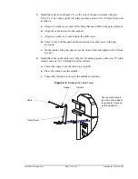
Slide the spring crank along the mainshaft until the mainspring pivot bar can be
removed and then remove the pivot bar and set aside (Figure 2.14).
Figure 2.14
Pivot Bar
To avoid serious injury, make sure that the mechanism is fully locked
in the up position. See “Locking, Unlocking, and Advancing the Gate
Arm” on page 49.
Remove the pivot bar
and set aside.
Slide the spring crank
along the mainshaft.
Summary of Contents for PosiDRIVE
Page 1: ...PosiDRIVE Security Gate Installation Operation and Maintenance Manual ...
Page 2: ......
Page 26: ...18 Removing the Enclosure Cap ZMA 330 Ver 6 PosiDRIVE Security Gate ...
Page 64: ...56 Aligning the Drive Mechanism ZMA 330 Ver 6 PosiDRIVE Security Gate ...
Page 68: ...60 Accessing the Distributor Resource Center ZMA 330 Ver 6 PosiDRIVE Security Gate ...
Page 90: ...82 Requesting a Repair ZMA 330 Ver 6 PosiDRIVE Security Gate ...
Page 94: ...86 Index ZMA 330 Ver 6 PosiDRIVE Security Gate ...
Page 95: ......


