


34
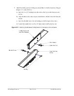
• Installing the Gate Arm
ZMA-330, Ver.6
PosiDRIVE Security Gate
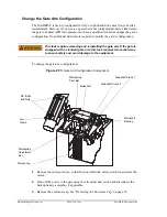
Change the Gate Arm Configuration
The PosiDRIVE is factory-configured for left- or right-hand drive based on your site’s
requirements; however, if you receive a gate that is not configured properly, either return
the gate to Federal APD for replacement or have a qualified technician change the gate’s
configuration. No additional hardware is required to modify the gate’s configuration.
To change the gate arm configuration:
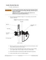
Figure 2.13
Gate Arm Configuration Components
1.
Remove the enclosure door, so that the door interlock safety switch de-activates the
motor.
2.
Turn off the power to the gate using the circuit breaker switch and disconnect the
backup battery assembly, if applicable.
3.
Remove the enclosure cap. See “Removing the Enclosure Cap” on page 16.
This task requires removing and reinstalling the gate arm. If the gate is
equipped with a standard gate arm, this task requires two technicians
to ensure safety and avoid damage to the equipment.
Mainspring
Pivot Bar
Mainshaft
Arm
Clamp
3/8” Bolts
and Nuts
Mainspring
Mainspring
Adjustment
Bar
Mainshaft
Bearing
Mainshaft Crank 1
Mainshaft Crank 2
Summary of Contents for PosiDRIVE
Page 1: ...PosiDRIVE Security Gate Installation Operation and Maintenance Manual ...
Page 2: ......
Page 26: ...18 Removing the Enclosure Cap ZMA 330 Ver 6 PosiDRIVE Security Gate ...
Page 64: ...56 Aligning the Drive Mechanism ZMA 330 Ver 6 PosiDRIVE Security Gate ...
Page 68: ...60 Accessing the Distributor Resource Center ZMA 330 Ver 6 PosiDRIVE Security Gate ...
Page 90: ...82 Requesting a Repair ZMA 330 Ver 6 PosiDRIVE Security Gate ...
Page 94: ...86 Index ZMA 330 Ver 6 PosiDRIVE Security Gate ...
Page 95: ......