37
4.4
C
HECK
/
MODIFY
S
ENTINEL
2
CHANNEL SETTINGS
In order for Sentinel 2 to operate correctly, any input channels must be set up, along
with any calibration data and also various other settings.
Select the Setup tab in IDT. Scroll to
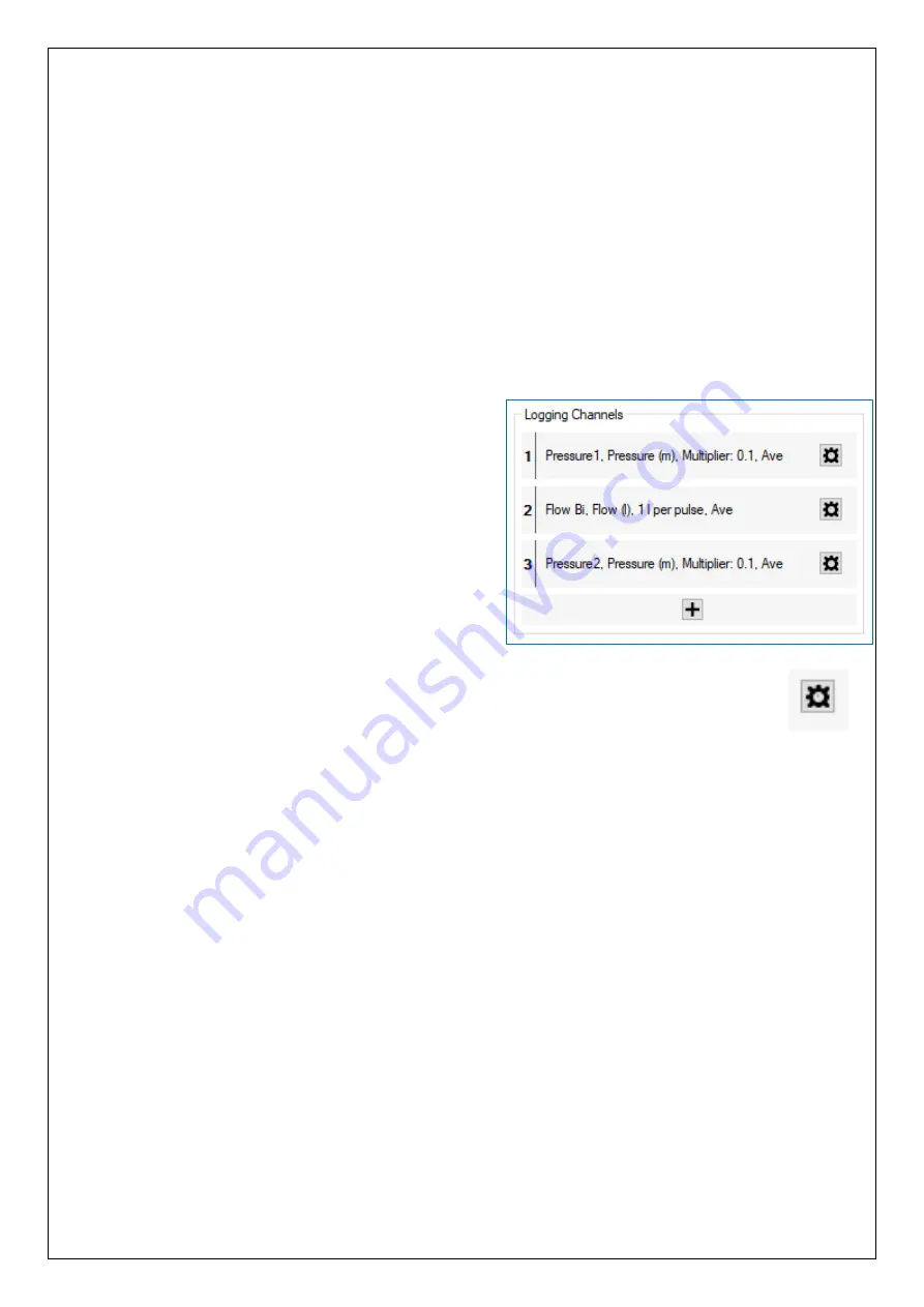
the “Logging Channels” panel.
This panel gives information regarding the type of interfaces for transducers fitted into
the unit.
Electrical interfaces can sometimes be general-purpose in nature, so the unit has to be
informed (by settings) of what type of transducers are attached. Also, it needs to be
informed of how to interpret numeric readings into physical measurements.
The diagram opposite represents the
transducers as inputs to a data-recorder which
has several channels of recording memory.
i.e.,
it is arranged as a set of “logging channels”.
The channels may be pre-configured by the
factory prior to shipment, but the installer is
responsible for confirming it is correctly
configured to suit the installation site.
Channels can be
added using the “+” button
(e.g., if other optional interfaces are fitted).
To modify an already existing channel, click on the relevant settings (cog) button.
For Sentinel 2 to operate correctly, the channels (where used) must always be set to the
following units of measure:
•
Pressure:
metres … although inputs work in raw units of
decimetres (1/10 m).
•
Flow:
litres per second.
For Sentinel 2 to operate with the DataGate and PressView websites, the unit must
always be set up with data presented
to the unit’s built
-in logger using the following
channels:
•
Channel 1: PRV inlet pressure (upstream pressure).
Sentinel2
uses the “Pressure 1” type of interface for this connector.
•
Channel 2: Flow.
Sentinel2 uses one of a set of interface types for this connector.
Each interface expects a voltage-free pulse output from the Flow meter.
o
Flow Uni (for a Unidirectional Flow meter)
o
Flow Bi (for a Bidirectional Flow meter)
•
Channel 3: PRV outlet pressure (downstream pressure).
Sentinel2
uses the “Pressure 2”
type of interface for this connector.


