DAZSCOPE SYSTEM
OPERATING MANUAL
9 september 2008
FASTLITE - [email protected]
Page 1: ...DAZSCOPE SYSTEM OPERATING MANUAL 9 september 2008 FASTLITE info faslite com ...
Page 2: ... 2 3 1 Hardware 9 2 3 2 Alignment 10 3 Software overview 13 3 1 Quick start 13 3 2 Software description 15 3 2 1 Menu bar 15 3 2 2 Control area 16 3 2 3 Display area 16 3 3 Setting up a measurement 16 3 3 1 Configuring the spectrometer 16 3 3 2 Configuring the ChirpScan algorithm 17 3 3 3 Editing the reference waveform 19 3 3 4 Selecting and starting a measurement 21 4 Optimizing the pulse duratio...
Page 3: ...reports 35 A 4 1 Screen captures 35 A 4 2 Parameters 35 B Dazzler parameters 36 B 1 Purpose 36 B 2 Parameters Files 36 B 2 1 Location and Names of Files 36 B 2 2 DazMain txt 37 B 2 3 DazCurrent txt 37 B 2 4 wave txt 37 B 2 5 Other Files 37 B 3 Changing Location of Parameters Files 38 B 4 Troubleshooting 39 B 4 1 Missing parameters 39 B 4 2 E mail reports 39 B 4 3 Screen captures 39 C Dazzler align...
Page 4: ...ulse is a phase only method Consequently the pulse shaper may be safely inserted at any stage within the laser chain see figure 1 1 for a typical architecture The DazScope is based on the pulse shaping device commercialized by FASTLITE under the trademark Dazzler and can be provided both as a an add on for existing Dazzlers or as a stand alone system The main part of this system is a complex softw...
Page 5: ...es in the basic mode a few operations from the user The DazScope is based on a characterization technique described in chapter 5 It must be underlined that as any phase only method this algorithm is not a pulse measurement technique comparable with the FROG or SPIDER techniques the DazScope is only relevant for pulses with sufficiently regular spectra and sufficiently smooth spectral phases The pu...
Page 6: ... re install the Keyspan driver the Labview run time support drivers and the Dazzler software see appendix chapter A 2 Install the spectrometer driver CDROM spectro drivers AvaSoft_7 x x USB2 zip this file must be first unzipped 3 In case the DazScope was previously installed use the uninstall option of the DazScope program group Start All Programs DzScope unistall DzScope 4 Install the DazScope So...
Page 7: ...2 1 Beam Orientations The angles indicated refer to the WB models Note that the polarization and the direction of the diffracted beam are different from the input beam Make sure that the output polarization fits your laser setup Input Optical Beam Reflection on the input face Reflection on the ouput face 14 3 6 1 Diffracted Beam Direct Beam Acoustic Wave Te02 Crystal Transducer Adaptation Circuitr...
Page 8: ...he proper trigger delay starts the panel Alignment and Calibration of the Dazzler Please refer to appendix C Power and Duration Parameters blue area 1 Set the power level to 0 5 2 Uncheck the CG box no constant gain 3 Select the new option in the action listbox 4 Select Load In A with the button switch 5 Set the add waveform button to off Amplitude parameters red area 1 Select the dials item in th...
Page 9: ...separate red and black curves If so check maximum delay and reduce second order parameter order 2 if necessary Trigger parameters Since all laser systems have different synchronization managements it is difficult to specify a universal process to set up the trigger parameters Here is however the most common way to proceed 1 Click in the Setup menu select Trig and mode this will open the correspond...
Page 10: ...rm appears in the left hand side display of the Loaded Waveform display right hand top corner of the Dazzler software window Once this is done the pulses are ready to be amplified Before going to the next step the amplified pulses must be compressed Some basic nonlinear effects SHG continuum generation in air or simple pulse characterization devices single shot autocorrelator must be used at this ...
Page 11: ... the beam unfocussed onto the non linear crystal A blue filter is supplied with the DazScope it can be inserted after the nonlinear crystal and might be useful to attenuate residual fundamental light A cable is supplied to trigger the spectrometer at a suitable repetition rate The trigger signal must be a TTL 0 5V pulse Various trigger and acquisition options can be chosen from the DazS cope softw...
Page 12: ...l the SHG spectral intensity is maximized Tweak then integration time and Dazzler diffracted power in order to get typically 10000 counts at maximum in the spectrum If no second harmonic spectrum is found If the spectrometer has an octave spanning spectral range e g the spectral range of the spec trometer is 350 900nm 1 Uncheck the Run button 2 Remove the blue filter 3 In the Spectrometer menu go ...
Page 13: ...e manual Chapter 2 Installation 4 Tweak the input beam direction to maximize the signal 5 Go back to the initial configuration the SHG signal shouldn t be far FASTLITE 9 september 2008 Table of contents 12 42 ...
Page 14: ...iguration window figure 3 2 Adjust the spectral range to the spectral width of the pulses to be characterized1 When the Advanced Mode checkbox is checked an extended window appears The trigger settings can be modified from this window When finished click on ok The SHG spectrum can now be recorded directly from the main window select the Spectrum item in the algorithm list and click on the run butt...
Page 15: ...al Chapter 3 Software overview Figure 3 1 Spectrometer initialization windows Figure 3 2 Spectrometer configuration window Left simplified panel Right advanced panel FASTLITE 9 september 2008 Table of contents 14 42 ...
Page 16: ...Menu bar File menu From this menu the current experimental results can be saved to a proprietary file format The user can also launch a data browser software to read the previously saved files and export the experimental data and or experimental parameters to ASCII and XML files Figure 3 4 Content of the File menu Save Measurement Results as saves the last completely acquired data to a binary file...
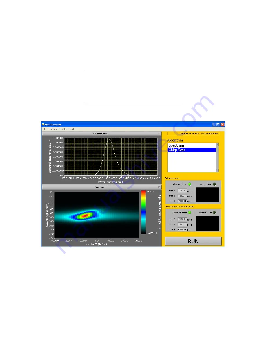
Page 17: ... is just a live record of the SHG spectrum and ChirpScan which is a phase optimization algorithm To launch one of these two actions the user must first select the appropriate item in the algorithm list and then press the RUN button To stop the algorithm while running uncheck this button 3 2 3 Display area This area displays the name of the current measurement and the experimental data 3 3 Setting ...
Page 18: ...e of the numeric control Open From File loads the parameters from an XML file Save To File save the current parameters to an XML file Reset To Default resets the parameters to their default values Make Default sets the current parameters as default parameters 3 3 2 Configuring the ChirpScan algorithm Double click on the ChirpScan item of the Algorithm listbox The configuration panel of the ChirpSc...
Page 19: ...rm ϕ2 min is the value of the Order2 Min control and ϕ2 max is the value of the Order2 Max control N is the number of discrete chirp values scanned over the range defined by the former second order values Units are in fs2 Some optional settings of the ChirpScan algorithm can also be defined The ChirpScan algo rithm was basically specified and designed to correct polynomial spectral phase up to the...
Page 20: ... WF menu and the Edit current Ref WF item This opens a window displaying the current reference waveform In the DazScope the reference wave form refers to the acoustic wave used when no optimizing algorithm is running It is the waveform displayed on the Dazzler panel when the Spectrum measurement is running The user must be aware that when the DazScope software starts the reference waveform is load...
Page 21: ...r by the position control if auto 0 Formula Advanced mode analytical formula Numerical Amp ASCII text file Please refer to the Dazzler manual for the description of the controls displayed in the Dials panels as well as for the Power Settings In the advanced mode the panels slightly change Please contact Fastlite for a complete description of the extended controls especially for the formulae Switch...
Page 22: ...ings Acceptable Energy Loss Factor maximum fraction 0 1 of the acoustic energy that can be out of the crystal Max power maximum power level The user is strongly recommended to leave the default values unchanged 3 3 4 Selecting and starting a measurement To set a measurement from the loaded measurements list select the corresponding item in the Algorithm listbox located in the control area and pres...
Page 23: ...correction is displayed on top of the 2D map and can be compared to the measured phase function more precisely to the second order derivative of the spectral phase If the corresponding option was selected in the configuration panel of the ChirpScan algorithm it is also possible to correct for the residual phase by selecting Correct residual phase numerically At this point the software leaves it to...
Page 24: ...e once again After a small number of iterations typically 5 the spectral phase should be flattened and ChirpScan experimental maps should converge toward a map exhibiting the following features maximum values are reached when the added second order is almost zero the map is symmetric with respect to the second order axis left right symmetry If these two criteria are not met there is still some res...
Page 25: ... correspond to a pulse lengthening of about a factor of two with respect to the shortest achievable pulse duration for a gaussian pulse1 All pulse durations and bandwidths are FWHM values For non gaussian pulses the phase coefficient values must be multiplied by a factor depending on the exact spectral shape For a supergaussian of order 6 this factor is about 3 4 Another point of interest is the v...
Page 26: ...in the amplifier without being strongly distorted e g a train of pulses will be obtained instead of two pulses On the contrary techniques that use phase only shaping produce only negligible non linear effects in a strongly chirped CPA amplifier In the ChirpScan method we take advantage of the ability of the AOPDF to program pure accurate second order phase to implement phase characterization using...
Page 27: ...econd order phase coefficient introduced by an AOPDF pulse shaper A Lorentzian fit confirms the validity of Equation 5 1 hyperbolic at large chirps Thanks to the asymptotic behavior of the SHG spectrum for high chirps it is possible to retrieve analytically the second derivative of the spectral phase from only a few experimental measurements For a given pulse of spectral phase ϕ ω we successively ...
Page 28: ... spectra vs chirp image it only shifts the image laterally The value of the shift corresponds directly to the chirp For the purely third order spectral phase pulse as the local chirp in a 3rd order is linear the image corresponds to a linear chirp optimization vs wavelength For a more complex phase the image is distorted but still corresponds for each wavelength to the chirp value that flatten the...
Page 29: ...er phase White dots second order derivative of the spectral phase as a function of wavelength Addedsecondorder fs2 SHG spectrum nm 3000 2000 1000 0 1000 2000 3000 380 385 390 395 400 405 410 415 420 0 1 0 2 0 3 0 4 0 5 0 6 0 7 0 8 0 9 1 Pure third order Addedsecondorder fs2 SHG spectrum nm 3000 2000 1000 0 1000 2000 3000 380 385 390 395 400 405 410 415 420 0 1 0 2 0 3 0 4 0 5 0 6 0 7 0 8 0 9 1 Pur...
Page 30: ...urth order Figure 5 5 Chirp scan pure fourth order phase White dots second order derivative of the spectral phase as a function of wavelength Addedsecondorder fs2 SHG spectrum nm 3000 2000 1000 0 1000 2000 3000 380 385 390 395 400 405 410 415 420 0 1 0 2 0 3 0 4 0 5 0 6 0 7 0 8 0 9 1 Sinusoidal phase Addedsecondorder fs2 SHG spectrum nm 3000 2000 1000 0 1000 2000 3000 380 385 390 395 400 405 410 4...
Page 31: ...ependent pulses of increasing or decreasing wavelengths with different pulse widths and different amplitudes see figure 5 7 Because of the time frequency uncertainty relationship t ν 1 this decomposition is limited to a finite number of such independent sub pulses that is to say to a finite number of non overlapping sub pulses in both time and spectral domains De facto this number is related to th...
Page 32: ...ficiency scales with the square of the instantaneous time intensity the SHG conversion efficiency of the sub pulse k is proportional to ηk Ek δτk 2 where Ek stands for the energy of the k th sub pulse which is to the first order equal to I ωk δω The SHG efficiency of the k th sub pulse is therefore proportional to I2 ωk ϕ00 ωk The k th sub pulse being a narrowband pulse of pulsation ωk its contrib...
Page 33: ... where the fastlite software CD has been inserted b this note applies only for the CD delivered with an Installers directory earlier distributions were operating differently A 2 Principles The components of the Dazzler software system are listed below indicating their origin models component source all driver for the USB to serial line adapter Keyspan all LabView run time support National Instrume...
Page 34: ...the USA19QW systems after no 84 use the USA19HS but better check with fastlite USA19HS cdrom Utilities Drivers USB Keyspan HS KeyspanUSA19hsWinV34 exe USA19QW cdrom Utilities Drivers USB Keyspan W and QW KeyspanUSA19wWinV31 exe perform a remove action if the driver was previously installed Make sure to restart the PC with the USB cable unplugged Then executing the same file KeyspanUSA19wWinV31 exe...
Page 35: ...cussion of these tools follows Acrobat Reader4 necessary tool for reading PDF files IrfanView a convenient free tool to capture screen windows and save them as files in different file formats Izarc a convenient tool to operate on ZIP archives These tools may be replaced by any other suitable tools that perform the same functions A 3 5 Dazzler application software There are several operations to pe...
Page 36: ...re A 1 Maintenance Window A 4 E mail reports In case of any problem please get in touch via e mail with as much information as possible in computer ready format at the address info fastlite com A 4 1 Screen captures For screen captures start Irfanview select Options then Capture use defaults Switch back to the window to be captured clic into it to bring it to the forefront and press control F11 Sa...
Page 37: ... generally kept in a different directory than the Dazzler software itself This allows to store them on a different partition than the system The location of that directory is defined in the file Dazzler Software Directory params txt One should find here a line of the form D generator SN Parameters Directory Path The location of that directory can be changed see section B 3 for details The paramete...
Page 38: ...d rarely have to be changed by hand Parameters should be changed during the software execution and saved upon exit B 2 4 wave txt This file keeps the main panel control values for re use on the next start Users wishing to operate the remote control options will use this file to find the names and syntax of the various knobs and controls When the stored waveform was using the files AMP TXT or PHASE...
Page 39: ...ur filesystem to find the directory containing your parameter files When you are INSIDE your parameter directory choose Select Current Dir The name of the selected directory should appear into the list of parameters sets and when this name is highlighted you should read its complete path below the list To allow the software to start automatically using your set of parameters you should then click ...
Page 40: ...h via e mail with as much information as possible in computer ready format at the address info fastlite com B 4 3 Screen captures To help us understanding your problem please send us as much screenshots as possible Irfanview software can be used to perform screen captures This software should have been installed by fastlite on your computer prior to shipment If you cannot find it for any reason pl...
Page 41: ... 1 Alignment The diagram on Figure C 1 shows the geometry of the crystal The z axis is perpendicular to the input face and is the direction of input optical beam The x direction is perpendicular to z and in the plane of diffraction The y direction is perpendicular to the plane of diffraction The acoustic beam region is patterned with dots The direction of the diffracted and direct non diffracted b...
Page 42: ...e position of the acoustic beam approximate dimensions 5 8mm2 Set the x and y positions so that the laser beam is approximately in the center of the diffraction region 5 Change the waveform of the Dazzler to produce a short acoustic signal by reducing the second order phase coefficient see Figure C 2 A typical signal on the oscilloscope is shown for this example The duration of this signal is the ...
Page 43: ...stment of the calibration C 3 Diffraction efficiency Put the detection diode on the direct beam A position Use an amplitude spectrum with a width of 100nm Extend the signal to cover the full range of delays by adjusting the second order phase coefficient Use the full power Observe the drop of signal on the scope The maximum drop should be at least 50 for a laser source of bandwidth smaller than 10...