SERVICE
SERVICE
Utility Sprayer 25' / 30' / 40' / 45'
Page 92
IMPORTANT: To help keep couplers
clean, always place them in a storage
position when they are not attached to
the tractor.
IMPORTANT: To prevent contaminants
from entering the hydraulic system,
filters must be installed at the tip of a
supply hose. Additional filters are not
recommended as they will restrict oil
flow and adversely affect cylinder
actuation time due to pressure drop.
Without a filter, large dirt particles can enter
the cylinder and settle against the top side of
piston (A) where they can cut the piston seal
as the cylinder retracts.
Replace Hydraulic Hoses
WARNING: Avoid hazards due to
escaping fluid under pressure. See
Hydraulic hoses between the lift cylinders
and hydraulic lock-up valve should be
inspected frequently for leakage, kinking,
cuts, cracks, abrasion, blisters, corrosion,
exposed wire braids, or any other signs of
wear or damage.
Worn or damaged hose assemblies can fail
during use and should be replaced
immediately.
See your Fast Ag Solutions dealer for
replacement hoses.
CAUTION: If an incorrectly rated hose
is used, machine damage, injury, or
death could occur.
If hoses are to be fabricated, ensure that the
hoses are rated at no less than 82,737 kPa
(827 bar) (12,000 psi) burst pressure
according to SAE Standard J517, 100R17
hose specification.
Incorrect hose length or routing can increase
the chance of hose wear or damage. Use the
old hose as a guide for length and hose
routing.
Incorrect fittings can damage mating parts or
cause leaks. Make sure to use steel fittings
approved for use by the hose’s manufacturer.
Use the correct size and thread.
Make sure hydraulic hoses and harnesses
do not interfere with moving parts. Relocate
hoses and harnesses and retain them with
clamps.
Tightening Hardware
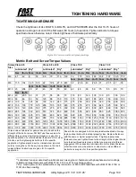
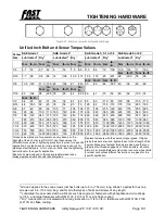
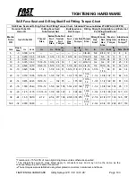
Tighten all bolts to torques specified in
otherwise noted.
Check tightness of hardware periodically.
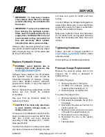
Pressure Gauge Replacement
Replace the pressure gauge and or the
pressure line if either is damaged or
malfunctioning.
To replace the gauge:
1.
Relieve pressure to the booms.
2.
Uninstall the pressure gauge by
loosening the mounting nut. (1)
3.
Replace gauge and tighten nut.
To replace the pressure line:
1.
Relieve pressure to the booms.
2.
Disconnect the pressure line (2) from
the gauge.
3.
Disconnect the pressure line from the
section valves. (3)
4.
Replace the line and be sure to route
it through the support bracket. (4)
5.
Reconnect the line to the gauge.
6.
Reconnect the line to the section
valves.
7.
Test operation.
Summary of Contents for UT3P25
Page 1: ...UT3P25 30 30BL 40 45 H40 H45 UTILITY SPRAYER OWNER S MANUAL...
Page 2: ...820037 25 30 40 45 Utility Sprayer 2023 11 15...
Page 8: ...Table of Contents Utility Sprayer 25 30 40 45 Page 8...
Page 32: ...SAFETY SAFETY Utility Sprayer 25 30 40 45 Page 32 General...
Page 41: ...HYDRAULIC FLOW HYDRAULIC FLOW Utility Sprayer 25 30 40 45 Page 41...

