2128N
Constant Fraction Discriminator
User Manual
© Copyright FAST ComTec GmbH
Grünwalder Weg 28a, D-82041 Oberhaching
Germany
Version 1.2, May 11, 2021
Page 1: ...2128N Constant Fraction Discriminator User Manual Copyright FAST ComTec GmbH Gr nwalder Weg 28a D 82041 Oberhaching Germany Version 1 2 May 11 2021...
Page 2: ...Version 1 0 May 11 2021 2 F ComTec GmbH...
Page 3: ...ustomer request the module can be modified to accept positive input signals The constant fraction composite signal is formed by the sum of a direct attenuated fraction f 0 4 standard signal path and a...
Page 4: ...ontpanel three position switch to select constant fraction with slow rise time reject CFRR basic constant fraction CFT or leading edge timing LET modes of operation OUTPUT WIDTH Front panel 22 turn sc...
Page 5: ...art of it may be reproduced by any means without prior written permission of FAST ComTec Gr nwalder Weg 28a D 82041 Oberhaching Germany Tel 49 89 665180 0 FAX 49 89 66518040 mail info fastcomtec com T...
Page 6: ...rols connectors and indicators 9 3 1 Front panel 9 4 Operation 10 4 1 General 10 4 2 Laboratory bench tests 10 4 2 1 Input 10 4 2 2 Operating mode 10 4 2 3 Delay cable 11 4 2 4 Walk trim 11 4 2 5 Outp...
Page 7: ...Table of Figures Fig 3 1 The Front Panel 9 Fig 7 1 The Circuit diagram 14 Fig 7 2 The Board 15 F ComTec GmbH 5...
Page 8: ...compensation of timing distortions due to both amplitude and rise time variations in the input signal Output signals are generated whenever the the input signal exceeds the selected threshold set by...
Page 9: ...ve voltage outputs providing 2V into 50 rise time 4 ns width adjustable by front panel trimming potentiometer the width then determines the internal dead time The maximum width should not exceed 300 n...
Page 10: ...emperature 0 0 C to 50 0 C Range 2 6 Delay cable Typical lengths for fast pulses 0 25 m to 1 m for pulses from slow detectors e g germanium detectors 1 5 m to 4 m For a better determination of the cab...
Page 11: ...R modes Walk adjust varies zero crossing discriminator adjustment Positive output connectors each supplies a TTL logic signal into a 50 Ohms load Width control sets positive output signal width also s...
Page 12: ...nd a delayed pulse delay time td external delay cable The derived time mark is theoretically independent of the pulse height of the input signal For a detailed description of the principle see e g D A...
Page 13: ...adjust potentiometer should be tried in order to find the optimum time resolution When the model 2128N is used with the intended detector time resolution has to be trimmed experimentally by successiv...
Page 14: ...e is either determined by a RC combination The output of IC7 goes to the clock enable input of a second master slave flip flop IC8 second half of the 10H131 The output of IC8 is converted by the follo...
Page 15: ...h a fixed output width for the negative output On customer request the width of the negative output can be enlarged within meaningful values regarding internal settings 6 4 Threshold In the standard v...
Page 16: ...Diagrams 7 Diagrams 7 1 Circuit diagram Fig 7 1 The Circuit diagram 14 F ComTec GmbH...
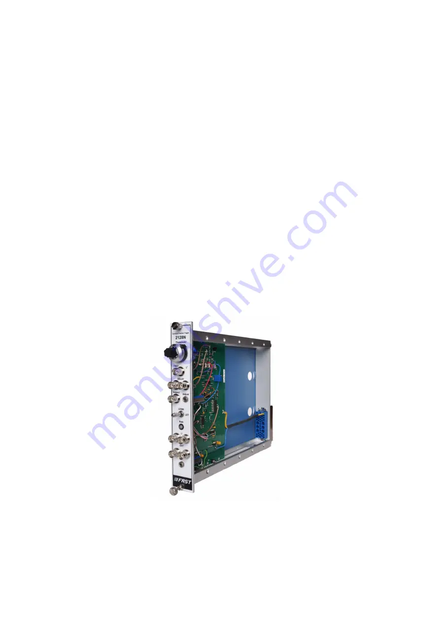
Page 17: ...7 2 Board Fig 7 2 The Board F ComTec GmbH 15...