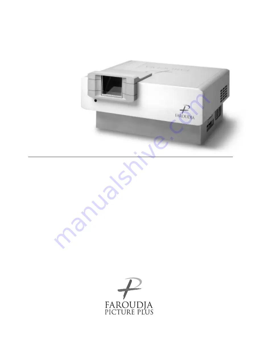
background image

Home Theater Optimized

FDP-DILA2

Installation and 

Operations Manual

NOTICE: THIS PROJECTOR HAS BEEN SIGNIFICANTLY

MODIFIED AND OPTIMIZED TO PRODUCE VERY HIGH

QUALITY IMAGES USING THE FAROUDJA PROCESSOR.

ANY CHANGES MADE TO THESE SETTINGS CAN CORRUPT

THIS PROCESS. RESETTING THE OPTIMIZATION IS NOT

COVERED UNDER WARRANTY.

Summary of Contents for FDP-DILA2

Page 1: ...ns Manual NOTICE THIS PROJECTOR HAS BEEN SIGNIFICANTLY MODIFIED AND OPTIMIZED TO PRODUCE VERY HIGH QUALITY IMAGES USING THE FAROUDJA PROCESSOR ANY CHANGES MADE TO THESE SETTINGS CAN CORRUPT THIS PROCESS RESETTING THE OPTIMIZATION IS NOT COVERED UNDER WARRANTY ...

Page 2: ...y the manufacturer When the product is used on a cart care should be taken to avoid quick stops excessive force and uneven surfaces which may cause the product and cart to overturn damaging equipment or causing possible injury to the operator Slots and openings in the cabinet are provided for ventilation These ensure reliable operation of the product and protect it from overheating These openings ...

Page 3: ...ice or repairs to this product ask the service technician to perform safety checks to determine that the product is in proper operating condition The product should be placed more than one foot away from heat sources such as radiators heat registers stoves and other products including amplifiers that produce heat When connecting other products such as VCR s and personal computers you should turn o...

Page 4: ...he Power 31 2 Select the Input source to be Projected 32 3 Adjust the Screen Size Zooming 33 4 Adjust Focus 33 5 Setting the Screen Aspect Ratio 33 Turning off Image HIDE 34 Removing the Trapezoidal Distortion of the Image 34 Quick Alignment Function QUICK ALIGN 35 Displaying a Still Picture FREEZE 36 Zooming a Part of the Image DIGITAL ZOOM T W 36 Menu Operations 37 Basic Menu Operation 42 Changi...

Page 5: ...ote control unit RM M160G AA R6 size dry cell battery 2 for checking operation Power cord approx 8 2 ft approx 2 5 m Ferrite core 2 Personal computer connection cable approx 6 56 ft approx 2 m D sub 3 row 15 pin Video cable approx 6 56 ft approx 2 m Conversion adapter for Mac for Macintosh BNC RCA Conversion plug Hex wrench Plus one DVI 9ft ...

Page 6: ...itch When it is turned on the projector goes into stand by state and the STAND BY indicator on the control panel comes on Refer to page 32 ON The main power turns on OFF The main power turns off 6 Adjustable feet for adjusting the height and angle By extending the feet the projector angle can be adjusted up to 7 For details refer to Adjusting the Inclination of the Projector on page 16 7 Lens One ...

Page 7: ... details refer to Adjusting the Inclination of the Projector on page 16 w Air inlet This is the air inlet Do not cover or obstruct this slot e Control panel For details refer to Control Panel on the Projector on page 9 r Lens shift knob cap When you have mounted a lens that uses the lens shift function open this cap and rotate the lens shift knob to move the lens position For more information refe...

Page 8: ...ling effect causing heat to build up inside which could cause a fire or malfunction y Opening for replacing the light source lamp For replacing the light source lamp refer to Replacing the Light Source Lamp on page 58 u Fixing foot i Position selecting screw for ceiling mounting When using the projector in an upside down ceiling mounted position inverted top to bottom and right to left the positio...

Page 9: ... OPERATE button the projector is not turned on Wait until the projector enters stand by mode STAND BY indicator stays lit 4 PC button Use this button to select a device connected to the PC 1 PC 2 or DVI terminals Each time you press the button the selection alternates among PC 1 PC 2 and DVI PC1 PC2 or DVI will be displayed on the top right of the projected image This function can be disabled by t...

Page 10: ...e menu items this button only works for the keystone setting screen q KEYSTONE buttons Use these buttons to correct a trapezoidal distortion of the projected image Refer to page 35 w HIDE button Use this button to turn off the image on the screen temporarily Pressing it again restores the image to resume Refer to page 35 e LAMP indicator ON After the light source lamp has been used for more than a...

Page 11: ...onnected Input of external sync signals is automatically detected Detection of H V signals or Cs signals causes automatic switching to external sync The priority order is H V Cs Note When computer related signals are input the uppermost edge of the image may appear to bow if the sync signal input is composite sync Cs or G on sync signal In this case use separate sync signals for vertical sync V an...

Page 12: ...ht of the projected image This function can be disabled by the menu 6 ZOOM T W buttons Use these buttons to adjust the projected screen size T Tele The projected screen size decreases W Wide The projected screen size increases 7 FOCUS buttons Use these buttons to adjust the focus of the projected video image The focus point becomes more distant The focus point becomes nearer 8 MENU button Use this...

Page 13: ...the projection screen size to 4 3 or 16 9 u QUICK ALIGN Quick Alignment button Use this button to automatically align Horizontal and vertical position Tracking and Phase for the projected image During the automatic alignment Quick Alignment appears on the screen and disappears after alignment is finished Refer to page 36 The Quick Alignment function only works when the signal is input from the inp...

Page 14: ...owing Do not mix new and old batteries Do not mix different types of batteries as they differ in characteristics Place batteries so they match the polarities indicated to and to Be sure to put the minus end in first to avoid short circulating Use only designated batteries Remove the batteries if the remote is not to be used for a prolonged period When the batteries are exhausted replace them immed...

Page 15: ...storage temperature range 14 F to 140 F 10 C to 60 C When installing the projector observe the following Do not use the projector placed on its side Avoid using the projector placed on its side This could cause a malfunction Use the projector within the specified angle Do not use the projector inclined 30 horizontally left right This could cause color variation or shorten the lamp life Do not bloc...

Page 16: ...raise the projector The adjustable feet automatically extend To retract the feet push the levers and lower the projector slowly the projector is fixed at the position where you release the levers Leveling the projector Lift the projector rotate the rear adjustable foot and adjust the horizontal angle until the projector is level Y PB B Y PR R Y REMOTE Y C VIDEO R G B DVI H IN OUT V IN Adjustable f...

Page 17: ...en To correct this distortion use the KEYSTONE buttons on the projector Refer to Removing the Trapezoidal Distortion of the Image on page 35 Also correction is possible by using the Keystone menu Refer to Setting and Adjusting Other Functions OPTIONS on page 54 LAMP TEMP STAND BY HIDE PC VIDEO MENU KEYSTONE VOLUME PRESET ESCAPE ENTER OPERATE Correctable angle Up to approx 20 upward from the horizo...

Page 18: ... or other means to shield the light Set the projector horizontally on a surface that is within the range of adjustable angles up down adjustment angle 7 horizontal adjustment angle 1 5 If the keystone is adjusted the projected screen becomes smaller When hanging from the ceiling use a dedicated hanging fixture not supplied Optional Lenses This projector does not include a lens You can select one o...

Page 19: ... it 2 Loosen the SHIFT LOCK fixing bolt Use the hex wrench supplied 3 Rotate the LENS SHIFT knob to adjust the position shift amount of the projected screen Rotate it to the right The lens shifts upward Rotate it to the left The lens shifts downward 4 Tighten the SHIFT LOCK fixing bolt firmly Use the hex wrench supplied 5 Turn the cap to close it Projected screen position image by amount of shift ...

Page 20: ...l unit toward the remote sensor on the front or the rear of the projector The operable distance of the remote control unit is about 10 m for direct reception The remote control unit can be used by having it reflected on the screen In this case the total distance of A B should be about 10 m or less The operable angles of the remote control unit are 15 right and left and 15 up and down 15 15 15 15 B...

Page 21: ... ceiling mount and adjust the projector special expertise and technique are necessary Be sure to ask your dealer or a specialist to perform this work To turn the position selecting screw for ceiling mounting use a Phillips screwdriver with a 30 mm or longer shank The screw is located in the hole shown in the illustration Note When using the projector in a ceiling mounted position you should revers...

Page 22: ...n book of the computer The video signal output port is generally called as RGB port monitor port or video port If the computer monitor hybrid type or note type is used it may need to prepare for an external output port Also there will be the type to which an external output port cannot be installed DVI input During DVI input depending on the computer settings there may be no signal input or an err...

Page 23: ...er Lines Horizontal fre quency H kHz Vertical fre quency V Hz PC system PC98 VESA350 640 350 37 86 84 13 PC AT PC98 640 400 24 83 56 42 DOS V VGA 60Hz 640 480 31 47 59 94 DVI VGA 72Hz 640 480 37 86 72 81 VGA 75Hz 640 480 37 50 75 00 VGA 85Hz 640 480 43 27 85 01 SVGA 56Hz 800 600 35 16 56 25 SVGA 60Hz 800 600 37 88 60 32 SVGA 72Hz 800 600 48 08 72 19 SVGA 75Hz 800 600 46 88 75 00 SVGA 85Hz 800 600 ...

Page 24: ...nnecting the S video cable refer to How to attach the ferrite core on page 29 Memo When connecting a VHS device using a TBC or one which has one built in is recommended Use of an extension cable to connect a video device and the projector could cause video degradation When a signal with much jitter is reproduced on a VCR or special effect playback is performed the upper part of the image or the im...

Page 25: ...e or DTV format signal output device Memo Other devices with component signal output terminals DVD player NTSC etc can be connected DVD Digital Video Disc DTV format signals 480i 480p 720p 1080i can be input For DTV format signals which can be handled refer to Video signals on page 22 Y PB B Y PR R Y IN REMOTE Y C VIDEO R G B H IN OUT V HDTV devices BNC cable separately available To PR R Y To PB B...

Page 26: ...rse connection cable For details refer to RS 232C external control on page 74 RS232 or IR control of the Video Processor is also required if controling the projector Note When connecting the cable to the REMOTE terminal refer to How to attach the ferrite core on page 29 Y PB B Y PR R Y IN REMOTE Y C VIDEO R G B H IN OUT V Desktop type To RS 232C connector To RS 232C connector RS 232C reverse conne...

Page 27: ... B Y PR R Y IN R G B H IN V POWER Desktop type To PC 1 Personal Computer connection cable supplied To monitor connector To B To R To G Notebook type There are some notebook types which do not allow the computer s LCD to work if an external display is connected With such a notebook computer the LCD display and external display output need to be switched Desktop type To monitor connector Separate ca...

Page 28: ...le or infrared remote sensor extension unit which are sold separately ony if they are connected directly to the projector 1 Release the stopper at each end and open the ferrite core 2 Wind the cord around the ferrite core Attach the ferrite core about 3 cm from the end of the cord 3 Close the ferrite core with the cord inside until you hear it click shut Note When connecting connect the terminal w...

Page 29: ...t on heat or stretch the power cords otherwise they may be damaged Do not insert or pull out the plugs with a wet hand 1 Insert the supplied power cord into the power input terminal of the projector 2 Insert the main plug of the supplied power cord into a suitable wall outlet CAUTIONS Since the power requirement of the projector is high insert the power plug directly into a wall outlet Use the sup...

Page 30: ...C 2000 hours These lamp replacement times are only a rough guide as to how long the lamp will last if these modes are used from the beginning These are not guaranteed service lives Notes Although the LIGHT OUTPUT CONTROL MODE LOC and LIGHT POWER CONTROL MODE LPC electrically control the brightness of the lamp and extend the replacement time longer than that for the NORMAL MODE the service life of ...

Page 31: ...ll not work for approximately 1 minute from when the light source lamp is turned on Use the button after approximately 1 minute 2 Turn off the MAIN POWER switch after the STAND BY indicator changes to steady on OFF The MAIN POWER switch turns off and the STAND BY indicator goes off CAUTION Do not turn off the MAIN POWER switch during cool down mode the STAND BY indicator blinking Turn it off after...

Page 32: ...s projected When there is no signal from the selected input terminal No signal No Input is displayed When selecting a device such as a computer which is connected to the PC1 PC2 or DVI terminal Projector Press PC The input mode changes as follows every time the button is pressed PC1 PC2 DVI Remote control unit Press the PC1 PC2 or DVI button PC1 The image from the PC1 input terminal on the side of...

Page 33: ...projected within the screen without using the zoom function When using a 16 9 screen Press the W button When using a 4 3 screen Press the S button There is no button on the unit This setting can also be performed from the menu Refer to page 46 When using a screen with a 16 9 aspect ratio When set to S 4 3 If a 4 3 image is projected some parts of the top and bottom of the image may not be displaye...

Page 34: ... figure To cancel correction and restore the original screen press the PRESET button Adjusted value 0 Press the EXIT button to immediately remove the keystone display Notes The trapezoidal distortion keystone can be adjusted from the option menu Refer to page 54 The range of the trapezoidal distortion adjustment is approximately 20 in the vertical direction Interference patterns may appear on the ...

Page 35: ...ls It does not work for the signals input from the AV IN terminal VIDEO Y C or COMP input terminal The quick alignment function is used to automatically adjust the Horizontal and vertical position Phase and Tracking of the projected image When using the quick alignment function to automatically adjust the image use a bright still picture It may not function correctly on a dark or motion picture If...

Page 36: ...e screen together with the level bar and magnifying power 1 0 1 2 1 4 1 6 2 0 2 5 3 2 4 0 When 15 sec is displayed in the menu Digital zoom will appear in approximately 15 seconds To zoom up or zoom down press the DIGITAL ZOOM T or W button on the remote control Moving the zoomed image While Digital zoom appears on the screen you can move the zoomed image with the cursor 5 2 3 button on the remote...

Page 37: ...200 Sleep time min Selectable sleep times If no signal condition continues for the period of selected time Unit Minutes the projector enters the stand by mode 15 30 60 OFF Language Language for on screen display Japanese English German Spanish Italian French Information Input Shows the terminal name selected by the VIDEO or PC button Y C VIDEO COMP PC1 PC2 or DVI Switcher Has no meaning This displ...

Page 38: ... Video Yes Image adj All reset No ENTER Position Disp Posi Menu Decoder AUTO NTSC NTSC NTSC4 43 PAL SECAM Menu Image adj Set up Color temp Options Language Information English Deutsch Español Italiano Français Menu Image adj Set up Color temp Options Language Information Input Switcher Source Lamp time PC1 CH 0 NTSC 123 h Language Page 2 Flip H Flip V RS 232C bps Sleep time min Page 1 OFF OFF 9600...

Page 39: ...gnals GREEN Adjusts the green level 0 to 255 the adjustable range varies depending on signals BLUE Adjusts the blue level 0 to 255 the adjustable range varies depending on signals All reset Reset above items to the factory set values Yes No Options Refer to page 54 Options 1 Menu display 15sec Menu disappears in 15 seconds ON Menu stays on Line display 5sec Line display such as VIDEO Y C PC1 or PC...

Page 40: ...F OFF ENTER ENTER Page 2 Flip H Flip V RS 232C bps Sleep time min Page 1 OFF OFF 9600 ENTER ON ON 19200 15 30 60 OFF Keystone 0 12 12 Set up 1 Tracking Phase Position Resize Clamp 123 12 ENTER ST BP 1 1 Panel Aspect ENTER 1 1 Panel Aspect Lamp control Normal LPC LOC Press 5 to select an item Press 2 3 to set or adjust the value 3 or ENTER Press 5 to select an item Press 2 3 to select Yes or No The...

Page 41: ... display 5sec Line display such as PC1 or PC2 appears on top right of the screen for 5 seconds when the VIDEO or PC button is pressed OFF Line display does not appear Lamp time display ON Displays when the lamp use time reaches 1000 hours when set in the LPC or LOC mode OFF Does not display when the lamp use time reaches 1000 hours when set in the LPC or LOC mode Keystone Press ENTER to enter the ...

Page 42: ...he screen When you selected Information in step 2 no submenu is available 4 Press the cursor button 5 or to select an item in the submenu When a Language has been selected in step 2 press to set the language 5 Press the cursor button 2 2 2 2 or 3 3 3 3 to set or adjust the value When an item which has the ENTER message has been selected in step 4 press the ENTER button to move to the next submenu ...

Page 43: ... W S T W T RM M160 REMOTE CONTROL UNIT SCREEN KEYSTONE W S MENU button ENTER button Cursor buttons 5 2 3 PRESET button EXIT button LAMP TEMP STAND BY HIDE PC VIDEO MENU KEYSTONE PRESET EXIT ENTER OPERATE MENU button ENTER button Cursor buttons 5 2 3 PRESET button EXIT button Menu Image adj Set up Color temp Options Language Information Contrast Brightness Color Tint Sharpness All reset Image adj C...

Page 44: ...der with the cursor button 5 or and press the ENTER button The Decoder submenu appears on the screen Video submenus 4 Set the color system with the cursor button 5 or AUTO Normally set to AUTO Factory set value The color system of a video signal being input is automatically identified and displayed in In B W Black White NTSC NTSC4 43 PAL or SECAM will be displayed It is not always displayed For ex...

Page 45: ...utton 5 or and press 3 3 3 3 or the ENTER button The Set up 1 submenu appears on the screen 3 Select Set up 2 with the cursor button 5 or and press 3 3 3 3 or the ENTER button The Set up 2 submenu appears on the screen 4 Select Screen or HDTV with the cursor button 5 or 5 Adjust the Screen aspect ratio or HDTV format with the cursor button 2 2 2 2 or 3 3 3 3 To adjust multiple items repeat 4 and 5...

Page 46: ...r Phase with the cursor button 5 or 4 Adjust the tracking or phase with the cursor 2 2 2 2 or 3 3 3 3 Adjust the tracking and phase of the picture image being projected To adjust the phase first check for correct tracking adjustment To adjust multiple items repeat 3 and 4 5 Press the EXIT button to return to the previous menu or press the MENU button to exit the menu mode Note A dim image could be...

Page 47: ...s on the screen 3 Select Set up 2 with the cursor button 5 or and press 3 or the ENTER button The Set up 2 submenu appears on the screen 4 Select Deinterlace with the cursor button 5 or 5 Select the Deinterlace function mode with the cursor button 2 or 3 Video When watching images recorded with a video camera Film When watching images recorded on film AUTO The setting is changed automatically 6 Pr...

Page 48: ...l items in the Image adj submenu are reset to the factory set values and the menu returns to the previous one To exit the All reset submenu without performing All reset select No with the cursor button 3 and press the ENTER button To be continued on the next page Image adj Contrast Brightness Color Tint Sharpness All reset 12 12 12 12 1 ENTER Image adj Contrast Brightness Sharpness All reset 12 12...

Page 49: ...r GREEN or BLUE with the cursor button 5 or 6 Fine adjust the color temperature with the cursor button 2 2 2 2 or 3 3 3 3 To adjust multiple items repeat 5 and 6 To perform All Reset In the Color temp submenu select All reset with the cursor button 5 or and press the ENTER button Then the All reset submenu appears on the screen Press the cursor button 2 to select Yes and then press the ENTER butto...

Page 50: ... adjusted Menu The menu position can be adjusted 5 Press the cursor button 5 5 5 5 2 2 2 2 or 3 3 3 3 to move the video screen display or the menu Repeat 4 and 5 to move both video screen display and menu positions Factory set value 6 Press the EXIT button to return to the previous menu or press the MENU button to exit the menu mode Set up 1 Position Gamma Aspect ratio Decoder Page 2 ENTER ENTER E...

Page 51: ...utton to return to the previous menu or press the MENU button to exit the menu mode Adjustment item Button Adjustment content Gamma 2 or 3 The image Gamma projected on the screen can be changed Down Suitable for projecting the video programs Cinema Normally use in this mode Up Suitable for projecting the cinema programs Aspect ratio 2 or 3 Sets the vertical to horizontal ratio 4 3 or 16 9 of the v...

Page 52: ...r button 5 5 5 5 or 4 Choose 1 1 Panel or Aspect with the cursor button 2 2 2 2 or 3 3 3 3 5 Press the EXIT button to return to the previous menu or press the MENU button to exit the menu mode Changing the Clamp pulse position PC Menu Mode Only When the image is too dark or bright or when the image is unstable switching the position may improve the image quality Normally set to BP 1 Press the MENU...

Page 53: ...bmenu select Page 2 with the cursor button 5 or and press the ENTER button To return to the Page 1 submenu from the Page 2 submenu select Page 1 with the cursor button 5 or and press the ENTER button To adjust multiple items repeat 3 to 4 To reset the keystone trapezoidal distortion of the picture image to the original setting press the PRESET button when the Keystone submenu appears on the screen...

Page 54: ...nal setting factory set value 0 press the PRESET button when the Keystone submenu appears on the screen To exit the keystone submenu press the EXIT button Lamp control ENTER Press ENTER to enter the lamp control submenu Normal Used as a normal lamp LPC Automatically controls the power used by the lamp and increases it in steps When this mode is used the brightness starts at approximately 70 The de...

Page 55: ... being used Source Shows the projected image s type of video signal Video menu mode Resolution Shows the resolution of the video signal being received PC menu mode It may not be displayed correctly with some input signals Frequency H Shows the horizontal frequency of the video signal being received PC menu mode Frequency V Shows the vertical frequency of the video signal being received PC menu mod...

Page 56: ...r the projector may be damaged 1 Turn off the main power switch and disconnect the power cord from both the projector and the wall outlet In stand by state the STAND BY indicator lights on place the MAIN POWER switch of OFF position 2 Loosen the fuse holder to remove it To loosen the fuse holder use a Phillips screwdriver 3 Remove the fuse from the fuse holder you just removed 4 Install the new fu...

Page 57: ...ment of the lamp is required as follows Projecting after the lamp has been used for more than 900 hours NORMAL MODE Note If the projector is not put in stand by mode or turned off it can be used until 2010 hours is reached When the lamp use time reaches 900 hours The LAMP indicator lights on the projector When starting to project after 900 hours has been exceeded Lamp replacement appears on the sc...

Page 58: ...ur dealer EXIT 1000 h Lamp replacement When the lamp use time reaches 1000 hours 1000h and Lamp replacement appear on the screen The messages will disappear when any button is pressed The time after which the display appears can be set with the OSD menu When the lamp use time exceeds 1900 hours The LAMP indicator blinks on the projector Lamp replacement appears on the screen To cancel this message...

Page 59: ...he screws are fitted so that they do not come off the lamp replacement opening cover 2 Loosen the screws raise the handle and pull out the light source lamp Loosen the two screws with a flat end screwdriver Note The screws are fitted so that they do not come off the light source lamp To be continued on the next page Screw Lamp replacement opening cover Be careful not to damage the claw Screw Light...

Page 60: ...ce lamp hold it by the plastic part Never touch the metal part or the front glass surface 4 Replace the lamp replacement opening cover and fasten the screws Fasten the two screws with a flat end screwdriver CAUTIONS Install the light source lamp and close the lamp replacement opening cover correctly otherwise a safety switch is activated to prevent the projector from operating If the claw on the l...

Page 61: ...hin 2 seconds of the previous button When you make a mistake in button operations return to the beginning of the sequence To check the lamp time on the menu press the MENU button and select Information with the cursor button 5 or The lamp use time is indicated in the item Lamp time Video main menu PC main menu CAUTION Reset the lamp use time only when you have replaced with a new light source lamp...

Page 62: ...r goes into an warning state the OPERATE and STAND BY indicator blink etc Therefore regularly clean the filter For the warning indication refer to page 67 3 Clean the filter Clean the filter with a neutral detergent wash it in water and then dry it in the shade CAUTIONS Put on rubber gloves when using neutral detergent After you have washed the filter in water make sure the filter is completely dr...

Page 63: ...ve any blocking objects and turn on the MAIN POWER switch again 6 7 32 Video image does not appear Is the correct input selected Select the correct input with the VIDEO and PC buttons 9 13 Are devices connected correctly Connect devices correctly 11 22 Are signals being supplied from the connected devices Set connected devices correctly Are input signals scanning frequency etc appropriate Check if...

Page 64: ... the DIGITAL ZOOM T button on the remote control pressed Press the PRESET button to restore the original video screen 12 37 Color is poor or unstable Is picture quality color density etc adjusted correctly Adjust picture quality on the menu 49 Is the correct color system selected Set the color system to AUTO or to the correct dedicated color system 45 Are signals scanning frequency etc of the conn...

Page 65: ...unplug the power cord from the wall outlet 2 Take an action according to the number No 4 Set the filter in place Then leave the projector until it cools down No 5 Check that nothing is blocking the air inlet nor outlet and wait until the inside cools down No 6 Check that nothing is blocking the air inlet nor outlet and wait until the inside cools down No 7 Leave the projector until it cools down 3...

Page 66: ...in the acceptable range other items such as resolution are out of the projector s specifications The selected input mode input terminal name is shown in the first line of the message Input the video signals that satisfies the projector s specifications 22 23 70 When the FREEZE button is pressed this message appears for a few seconds When a button not acceptable is pressed during freezing this mess...

Page 67: ...ours and until it reaches 1000 hours The message is cleared by pressing any button Arrange for a new lamp lamp unit or replace the lamp early 44 46 Displayed when the lamp control setting is set to NORMAL MODE When the lamp use time reaches 1000 hours the word Warning blinks on the screen To cancel this message press the EXIT button However the same message will appear every hour If the power is t...

Page 68: ...isplayed when the lamp control setting is set to LIGHT OUTPUT CONTROL MODE LOC or LIGHT POWER CONTROL MODE LPC Appears every time the projector is turned on after the lamp use time has exceeded 1900 hours and until it reaches 2000 hours The message is cleared by pressing any button Arrange for a new lamp lamp unit or replace the lamp early 44 46 Displayed when the lamp control setting is set to LI...

Page 69: ...resolution during RGB input 1000 TV lines Horizontal resolution aspect ratio 4 3 during video input Scanning frequency Horizontal frequency 15 kHz 105 kHz Vertical frequency 50 Hz 100 Hz Audio power output 1 W monaural 1 5 8 4 cm round type micro speaker 1 AV IN Y C 1 line mini DIN 4 pin 1 for S video VIDEO 1 line BNC 1 for composite video 1 line BNC 3 for computer DTV or video Y B Y R Y Component...

Page 70: ...Machines Corporation Macintosh is a registered trademarks of Apple Computer Inc VESA is a trademark of the non profit organization Video Electronics Standards Association All other product names mentioned herein are used for identification purposes only and may be the trademarks or registered trademarks of their respective companies Power requirements 120 V AC 50 60 Hz Power consumption 7 A Allowa...

Page 71: ...side dimensions Top Front Side Unit inch LAMP TEMP STAND BY HIDE PC VIDEO MENU KEYSTONE PRESET EXIT ENTER OPERATE 5 1 4 133 22 430 18 444 19 300 22 430 15 1 2 2 1 8 2 1 8 53 10 605 11 703 19 300 10 1 8 256 2 7 8 70 111 703 ...

Page 72: ... 3 Blue 11 GND 4 N C 12 N C 5 N C 13 H SYNC 6 GND Red 14 V SYNC 7 GND Green 15 N C 8 GND Blue 1 2 3 4 5 6 7 8 17 9 11 13 15 10 12 14 16 18 19 20 21 22 23 24 Pin number Signal name Pin number Signal name Pin number Signal name 1 T M D S Data2 9 T M D S Data1 17 T M D S Data0 2 T M D S Data2 10 T M D S Data1 18 T M D S Data0 3 T M D S Data2 Shield 11 T M D S Data1 Shield 19 T M D S Data0 Shield 4 No...

Page 73: ...e the following data format Header Designates the head of data and the kind of data 21h Control command to the projector 3Fh Query to the projector Asking command ID 1 fixed SP Designates the delimiter for ID Command and Parameter 20h CR Designates the terminal of the data 0Dh is not necessary when Asking command 2 2 Response data format from the projector to the computer Upon executing the receiv...

Page 74: ...trol commands that can be sent from the computer are as follows Keystone Numeric value can range from FF80 to 0080 Operation mode Only Asking command is possible Character Hex Meaning 0 30 OFF 1 31 ON Character Hex Meaning 0 30 Y C 1 31 VIDEO 2 32 COMP 3 33 PC1 4 34 PC2 5 35 DVI Character Hex Meaning 0000 30h 30h 30h 30h Stand by mode 0001 30h 30h 30h 31h Power on mode 0002 30h 30h 30h 32h Cool do...

Page 75: ... 0 cm 9 88 3 01 10 79 3 29 160 approx 406 4 cm 10 56 3 22 11 52 3 51 170 approx 431 8 cm 11 22 3 42 12 24 3 73 180 approx 457 2 cm 11 88 3 62 12 96 3 95 190 approx 482 6 cm 12 57 3 83 13 68 4 17 200 approx 508 0 cm 13 22 4 03 Projection screen size Diagonal length Approximate projection distance unit ft m For 4 3 aspect ratio screens For 16 9 aspect ration screens 55 approx 139 7 cm 6 00 1 83 60 a...

Page 76: ...03 14 64 400 approx 1016 0 cm 50 36 15 35 54 86 16 72 450 approx 1143 0 cm 56 63 17 26 61 65 18 79 470 approx 1193 8 cm 59 12 18 02 64 37 19 62 480 approx 1219 2 cm 60 37 18 40 500 approx 1270 0 cm 62 89 19 17 521 approx 1323 3 cm 65 52 19 97 Projection screen size Diagonal length Approximate projection distance unit ft m For 4 3 aspect ratio screens For 16 9 aspect ration screens Wide end Tele en...

Page 77: ...77 ...

Page 78: ...78 ...

Page 79: ...79 ...

Page 80: ...ucts to Faroudja transportation charges prepaid Faroudja s only liability with respect to products that do not meet the foregoing warranty and for which appropriate transportation arrangements have been made will be to repair or at Faroudja s option replace defective products or portions thereof THE FOREGOING WARRANTY IS IN LIEU OF ALL WARRANTIES EXPRESS IMPLIED OR STATUTORY REGARDING THE PRODUCTS...

Reviews: