background image

FARO

®

Laser Scanner Manual

85

Chapter 7: Controller Software

This manual compass measurement only affects the output on this screen and 
it is not necessary for the orientation data measured during scanning. During 
scanning an orientation measurement is performed automatically.

The accuracy of compass measurements can be affected by magnetic or 
other environmental interference. An indicator of the strength of environmental 
interference and thus of the current compass measurement accuracy is the 
displayed 

Horizontal field strength

 of the magnetic field. The typical strength 

of the earth's magnetic field depends on geographical position and varies from 
0.3 to 0.6 gauss (G). The displayed horizontal field strength is lower than the 
absolute field strength because of the inclination of the field. For example, the 
typical horizontal field strength for Europe is about 0.2 gauss.

If the measured field strength differs significantly from the expected field 
strength, there might be a strong artificial magnetic field near the scanner that 
probably affects the measurement. To get the most reliable orientation data for 
the scan registration, avoid positioning the scanner near to strong magnetic 
fields. If the measured horizontal field still significantly differs, you can switch 
the use of the compass data to OFF.

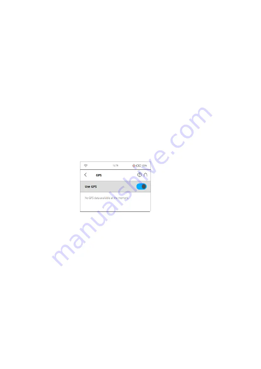
GPS

Figure 7-61: GPS

The position information of the scanner‘s position provided by the built-in GPS 
sensor is attached to each scan and is automatically used for the scan 
registration in SCENE, if the use of the GPS sensor is switched ON.

Use GPS

 - Turn the GPS sensor ON or OFF. Unlike the other sensors, GPS 

data is only recorded and attached to each scan if this sensor is turned ON. 
This function is also available under Scanning Parameters. 

 For more information, see 

Setting the Scanning Parameters

 on page 38. 

After the GPS sensor is switched ON, it automatically begins searching for 
GPS satellites. Note that it can take some minutes to find all the available 
satellites and to determine a precise position information. It is recommended 
to switch the GPS sensor OFF if it is not needed or if a GPS signal is not 
available (for example, if you are scanning indoor).

GPS information

 - Provides information about the currently measured GPS 

coordinates latitude, longitude and the altitude as well as the UTC time of the 
last satellite contact and the number of satellites that are currently in view. The 
GPS receiver needs the signal of at least three satellites to calculate a 2D 

Summary of Contents for FocusM 70

Page 1: ...NUAL SEPTEMBER 2017 For more information contact Synergy Positioning Systems or visit the Synergy Positioning Systems website at www synergypositioning co nz All branches Phone 0800 867 266 Email info...

Page 2: ...HNOLOGIES INC REGARDLESS OF THE FORM OF ACTION SHALL NOT EXCEED THE PURCHASE PRICE OF THE MATERIALS DESCRIBED HEREIN THE INFORMATION CONTAINED IN THIS MANUAL IS SUBJECT TO CHANGE WITHOUT NOTICE AND DO...

Page 3: ...havior when charging cradle connected to power source 19 Chapter 6 Getting Started 6 1 Charging the Battery 20 6 1 1 Charging the Battery in the FARO Laser Scanner 20 6 1 2 Charging the Battery with t...

Page 4: ...6 On Site Registration 100 7 4 7 Service 102 7 5 View Scans 109 7 6 Online Help and Notifications 111 7 6 1 Notifications 111 7 6 2 Help 111 Chapter 8 Special Scanning Modes 8 1 Scanner Control 112 8...

Page 5: ...or unit 144 10 6 Multi Sensor 144 10 7 Interface Connection 144 10 8 Deflection unit 145 10 9 Ambient Conditions 145 10 10 Notes 145 10 11 Scanner Dimensions 146 10 12 Scanner Mount Dimensions 147 Cha...

Page 6: ...FARO Laser Scanner Manual 1...

Page 7: ...dhered to could result in personal injury or death Do not proceed beyond a WARNING notice until the indicated conditions are fully understood and met CAUTION A CAUTION notice denotes a hazard It calls...

Page 8: ...ote A NOTE denotes additional information that aids you in the use or understanding of the equipment or subject They are not used when a WARNING or CAUTION is applicable They are not safety related an...

Page 9: ...y of millions of 3D measurement points Unless otherwise stated we use the term FARO Laser Scanner for any of the FARO Laser Scanner FocusM 70 FocusS 70 FocusS 150 or FocusS 350 The FocusM 70 FocusS 70...

Page 10: ...g scanned scattered light from surrounding objects is then reflected back into the scanner Figure 2 2 Laser Deflection To measure the distance FARO Laser Scanner uses phase shift technology where cons...

Page 11: ...oint cloud consists of millions of scan points The laser scans are recorded on a removable SD card enabling easy and secure transfer to SCENE FARO s point cloud manipulation software This manual provi...

Page 12: ...FARO Laser Scanner Manual 7...

Page 13: ...r transport and carry case Laser scanner An SD card is already inserted in the scanner Power supply unit Power Block battery FARO Quick Release Mirror cleaning liquid for optics SD card reader Power D...

Page 14: ...r cable Recommended additional equipment Tripod Spare battery Retain all packing materials as you may need them later The SD memory card a charged Power Block battery and a tripod are the minimum requ...

Page 15: ...uitably trained users after they have read and understood this manual and considered any hazard involved We recommend that operators participate in the trainings offered by FARO 4 4 General Safety Inf...

Page 16: ...fore bringing it from a cold to a significantly warmer environment This allows the condensation to form on the bag and not inside the scanner If you do not have the possibility to pack the scanner air...

Page 17: ...time remove the battery Store the battery only when it is charged at least 60 charge state It is recommended to charge the battery once a year when it is stored longterm Storage temperatures 20 C 4 F...

Page 18: ...the FARO Laser Scanner can rotate freely and will not hit any objects during the scan CAUTION The FARO Laser Scanner may only be used when set on a flat and stable surface Injuries may result if the...

Page 19: ...n is provided that allows you to carry such a battery without further paperwork The maximum battery energy a single person can carry is 200 Wh NOTE Please make sure that the total energy content of al...

Page 20: ...afety Precautions Objects have fallen onto the product The product does not operate normally by following the operating instructions The product exhibits a distinct change in performance The required...

Page 21: ...Pressing and holding the button more than 3 seconds will switch the FARO Laser Scanner off without shutting down Use this option only in exceptional cases for example if the shutdown mechanism does n...

Page 22: ...anual 17 Chapter 5 Parts and their Functions 5 1 2 Battery Side Figure 5 5 Battery Side of the FARO Laser Scanner Battery compartment cover Socket to plug an external power supply LED showing battery...

Page 23: ...ns see Mechanical Safety on page 13 and Cleaning Instructions for Optics on page 129 Scanner mount Reference area used for self referencing the distance measurements while scanning 5 1 4 Bottom Side F...

Page 24: ...cover release mechanism 5 2 Power Dock Battery Charger Figure 5 8 Power Dock Battery Charger Safety clamps To insert the battery drag downwards Connectors Power socket Power LED for LED specifications...

Page 25: ...power supply unit can be used in many countries It is compatible with a 100 V AC to 240 V AC 50 60 Hz power source Use a plug adapter when necessary 6 1 1 Charging the Battery in the FARO Laser Scanne...

Page 26: ...before connecting 5 If the FARO Laser Scanner is turned off the LEDs of the scanner will start blinking blue while charging The LEDs will stop blinking and will illuminate to constant blue when the b...

Page 27: ...power supply unit as well as to a power outlet Check the input voltage on the type label before connecting 3 The LED of the Power Dock battery charger illuminates blue when power is connected correctl...

Page 28: ...y press the charger interlock mechanism and remove the battery out of position 6 1 3 Tips for Using the Battery Charge the battery the day it is to be used or on the day before A charged battery that...

Page 29: ...r may only be used when set on a flat and stable surface If using a cart move the setup with special care Never move the cart by pulling at the power cables Pushing or pulling of the cart with too muc...

Page 30: ...the tripod 3 Attach mount plate underneath the scanner 4 Mount the scanner 1 Set up the tripod Extend the legs of the tripod and lock the leg angle clips Ensure that the tripod is stable the feet are...

Page 31: ...ce facing the platform of the tripod If it sticks out of the surface use the S3 hex key to recess it 2 Mount the base plate on the tripod using the central 3 8 threaded stud of the tripod Tighten it m...

Page 32: ...ter 6 Getting Started 4 Use the S3 hex key to tighten the set screw of the base plate completely against the platform of the tripod The base plate is now securely tightened on the tripod s platform an...

Page 33: ...t 1 Attach the mount plate to the scanner using the central 3 8 screw Do not tighten firmly in this first step 2 Put the S3 hex key shown here in silver as an interlock into one of the three openings...

Page 34: ...plate 3 Turn the scanner to change its orientation so that it fits your individual needs for the scan Then tighten the threaded collar firmly Test if the scanner is correctly locked in place by gently...

Page 35: ...cards with a capacity of more than 32 GB cannot be formatted with the Windows format function as Windows will format those cards in its own file system The Windows file system is not supported by the...

Page 36: ...ictures of captured scans will be saved to this folder The folder will be created automatically as soon as you start a scan See Starting a Scan on page 48 Projects Scan projects information will be sa...

Page 37: ...the SD Card To remove a SD card from the scanner open the SD card slot cover and lightly push the memory card Do not eject the memory card while it is busy Take care that the memory card does not pop...

Page 38: ...acitive stylus to navigate through the user interface 6 5 Initial Scanner Settings This chapter gives you a brief description on how to set up initial scanner settings using the scanner s controller s...

Page 39: ...Getting Started Figure 6 16 Language Selection Screen Select the language by tapping the corresponding button The selected language will be highlighted If the list of available languages exceeds the...

Page 40: ...automatic time zone settings 24 Hour Clock Tap to set the time format The scanner can display time either in the 24 hour or the 12 hour clock format Slide the button to ON to select the 24 hour clock...

Page 41: ...You can select between the date formats DD MM YYY MM DD YYYY or YYYY MM DD where YYYY is the year DD the day and MM the month The selected format will be highlighted 6 5 4 Changing Date and Time Figu...

Page 42: ...f Length Lengths will be displayed by the controller software either in meters or in feet Select the favored unit of length by tapping the corresponding button Temperatures will be displayed either in...

Page 43: ...ou would provide and enter project information before starting with your scan project This will be described later For more information see Scan Projects and Clusters on page 68 6 6 1 Setting the Scan...

Page 44: ...ution in megapoints and the selected quality Tap the button to change these values Horizontal and Vertical Scan Range Displays the scan range with the horizontal and the vertical start and end angles...

Page 45: ...of the scan in points horizontally x vertically The vertical size may only be changed by setting a new resolution or by changing the scan area angle Scan Duration Scan File Size Expected scan time and...

Page 46: ...lity Home Parameters Resolution Quality Figure 6 24 Change Scan Resolution and Quality Resolution The resulting scan resolution You can choose among 1 1 1 2 1 4 1 5 1 8 1 10 1 16 1 20 and 1 32 Quality...

Page 47: ...itch off the scanner nor change the quality between the recordings of these scans Setting the Scan Range Home Parameters Horizontal Vertical Figure 6 25 Setting the Scan Range Vertical area The size o...

Page 48: ...See the SCENE user manual for more information Use Compass Enable or disable the automatic use of the data of the built in compass for the scan registration in SCENE The data of the compass is always...

Page 49: ...in which the integrated color camera determines the exposure for taking the color photos if colored scan recording is switched on Even Weighted Metering To determine the exposure settings the camera...

Page 50: ...e 6 29 Exposure metering area for a limited vertical scan area set to e g 10 to 90 Zenith Weighted Metering With zenith weighted metering the camera will use the light information coming from above th...

Page 51: ...g due to duplicate scan points Clear Sky Enables the dynamic sky filter During scanning this hardware filter will remove scan points resulting from scanning empty spaces in the sky Distance Range The...

Page 52: ...1 5mm 10m 40 960 1 2 1x 174 8 0 04 35 3 1mm 10m 20 480 1 2 2x 174 8 0 08 09 3 1mm 10m 20 480 1 2 3x 174 8 0 15 19 3 1mm 10m 20 480 1 2 4x 174 8 0 29 38 3 1mm 10m 20 480 1 2 6x 174 8 1 55 32 3 1mm 10m...

Page 53: ...N and the scanning view will be displayed The scanner s LEDs blink red as long as the laser of the scanner is switched ON During scanning the scanner rotates clockwise by 180 If you are scanning with...

Page 54: ...f in the settings and a new screen appears with a preview picture of the captured scan Now you may move the scanner to the next scan position and start a new scan After having completed scanning and c...

Page 55: ...an Tap the Info button in the scan preview to view the scan properties Resume Scan button Resumes the previous scan Displayed only when a scan is paused Delete button Delete the viewed scan file Use t...

Page 56: ...e inclinometer at the tripod or the inclinometer screen Tap this button to get to the inclinometer screen 6 7 LED Behavior Scanner Status LED at Power ON OFF button Scanner off external power supply n...

Page 57: ...re the equipment in protective cases 1 Open the battery compartment cover 2 Release the interlock mechanism of the charger to release the battery 3 Remove the battery Close the battery compartment cov...

Page 58: ...FARO Laser Scanner Manual 53...

Page 59: ...signal Battery shows the status and charge state of the internal battery SD card is busy Do not remove the SD card from the scanner while it is busy otherwise you risk corrupting the data on the card...

Page 60: ...vious screen The name of the screen that is currently shown Errors and Warnings this button only appears if warning or errors are present Tapping the button opens a screen that informs about details o...

Page 61: ...ators Duplicate button Adds new scan profiles projects or operators by duplicating the selected list element Delete button Deletes selected list elements like projects scan profiles or operators This...

Page 62: ...t Backspace OK key applies your input and returns to the previous screen Cancel key returns to the previous screen without applying your changes Tapping on a character of the keyboard will enlarge it...

Page 63: ...Info box Tap the arrow button underneath HOME to show or hide the info box The info box informs about the currently selected operator project and scan profile It also shows information about the curre...

Page 64: ...or the scanning angles are the parameters used by the scanner for recording the scan data There are two ways to set the scanning parameters by changing them manually by selecting a scan profile which...

Page 65: ...lected Profile Shows the name of the selected scan profile Tap to select a scan profile If the scanning parameters differ from the selected profile altered is appended to its name Selecting a predefin...

Page 66: ...l 61 Chapter 7 Controller Software 7 3 2 Resolution and Quality Figure 7 40 Scan Parameters Resolution and Quality Displays the selected resolution in megapoints and the selected quality Tap the butto...

Page 67: ...62 Chapter 7 Controller Software 7 3 3 Horizontal and Vertical Scan Range Figure 7 41 Scan Parameters Scan Area Displays the scan range with the horizontal and the vertical start and end angles in de...

Page 68: ...uilt in sensors for the scan registration in SCENE 7 3 5 Scan with Color Switch colored scan recording on or off If switched on the scanner will also take color photos of the scanned environment with...

Page 69: ...is switched on Select between three exposure metering modes to meet the requirements of the current lighting conditions and to get best possible results for the area of interest Even Weighted Meterin...

Page 70: ...the horizon This mode is the default setting Compared to even weighted metering this mode will increase scan duration by approximately 14 seconds Figure 7 44 Horizon weighted metering If the vertical...

Page 71: ...light and exposure for objects at the ceiling of building e g for ceiling paintings in historical buildings Compared to even weighted metering this mode will increase scan duration by approximately 14...

Page 72: ...When HDR is enabled the larger number of captured images will result in a longer capturing time The processing time will be longer in SCENE The HDR Mode and Night Mode are both mutually exclusive Ena...

Page 73: ...the general scanner settings See General Settings on page 88 On Site Registration See On Site Registration on page 100 Service Opens the menu for scanner services like firmware updates backups or vie...

Page 74: ...scans to scan clusters and thus to automate the registration of the scans For more information on scan registration and combining scans to cluster see the SCENE user manual You can enter scan project...

Page 75: ...ard project that can be selected when working in no particular scan project The Default_Project is not deletable and you can not change its name or parent project Add a scan project or cluster To add...

Page 76: ...ill be added as a main project without parent projects Project Name The name of the item Tap to change the name A name must start with a letter and may contain letters digits and underscores Parent Pr...

Page 77: ...ed by the current scan number Initial Scan No Automatically increments with each successive scan Can be reset and can be used to indicate the number of scans per scan session Additional Info Additiona...

Page 78: ...of a project cluster select it and the list will be expanded with its clusters Proceed accordingly with further clusters Delete a scan project To delete a project or cluster select it in the list and...

Page 79: ...project will be highlighted To view or change details of the selected project tap its button once more To display available clusters of a project select it and the list will be expanded Proceed accord...

Page 80: ...can profiles see Factory Settings on page 108 for an overview of the available factory predefined scan profiles These scan profiles are read only and cannot be changed or deleted But you can of course...

Page 81: ...it The further settings in this view are similar to the settings of the scanning parameters For more information see Scan parameters on page 59 Editing a Scan Profile To edit a scan profile select it...

Page 82: ...cts or areas in very high resolu tion It is rec ommended to limit the scan area to the object or area of inter est else the scan might take very long to com plete Quality 3x 4x 4x 4x 4x 6x Vertical Ar...

Page 83: ...y Scan outdoors where the dis tances from the scanner to the main objects of interests are far Quality 4x 4x 4x Vertical Area 60 90 60 90 60 90 Horizontal Area 0 360 0 360 0 360 Inclinometer ON ON ON...

Page 84: ...To do this select the operator in the operators list Create an operator profile first if it does not already exist The information about the selected operator is then stored in the data of the next s...

Page 85: ...company providing the scanning service Department The department the operator works for Phone The operator s phone number Email The operator s email address Info Any additional information required by...

Page 86: ...on of the scanner See Compass on page 84 GPS Tap to view details about the current GPS position and accuracy See GPS on page 85 Altimeter Tap to view the currently measured altitude of the scanner s p...

Page 87: ...l shut down within the next minutes Fan cooling switches the scanner s integrated fan on or off If the temperature is above the critical limit please check if the fan is switched on If not please swit...

Page 88: ...Inclination Warning icon in the header bar is only visible when the current inclination of the scanner is above 2 the icon becomes yellow or the icon becomes red if the scanner is tilted more than 5 T...

Page 89: ...ng Parameters on page 38 You can monitor the current orientation of the scanner on this screen Initially when entering this screen the orientation is not displayed To see the current orientation of th...

Page 90: ...id positioning the scanner near to strong magnetic fields If the measured horizontal field still significantly differs you can switch the use of the compass data to OFF GPS Figure 7 61 GPS The positio...

Page 91: ...n this case the DOP values are low Higher DOP values indicate a poor satellite geometry which might have a negative effect on the position accuracy The current GPS status and signal quality is indicat...

Page 92: ...to use as the reference for the altitude measurements Move the scanner to this reference position enter any height you would like to use for this position and reset the altimeter to this reference hei...

Page 93: ...el enable or disable start on power modify display settings to optimize power usage See Power Management on page 90 Display Set the brightness of the screen or change the theme of the Home screen to D...

Page 94: ...more information see WLAN on page 91 Sounds The scanner has a built in speaker The scanner signals certain events with various sounds You can change the speaker volume here and switch the sound effec...

Page 95: ...nsaver appears by tapping the plus or minus buttons Deactivate the screensaver by setting the time to never When the screensaver is visible simply tap the screen to return into operation mode Dim disp...

Page 96: ...at appears We recommend using a stylus to calibrate the display If the calibration of the touch screen is corrupted you must reset the calibration of the display to its factory settings Shut down the...

Page 97: ...an files on the scanner SD memory card It is possible to turn WLAN off from a remote interface Since this might disable the connection to the remote interface a warning is displayed Status Tap this bu...

Page 98: ...e the available networks are displayed and can be selected IP settings Set a static IP Address or obtain one automatically through DHCP The IP settings determine whether an IP address is assigned by a...

Page 99: ...ecure connection https 172 17 16 23 in the address field of your web browser You will receive a security warning from the browser before connecting to the GUI confirm to proceed Figure 7 70 Scanner se...

Page 100: ...63 characters This is the default recommended option Encryption key The scanner network is encrypted with a WPA2 key Enter this key on your remote device when prompted to establish the connection to...

Page 101: ...7 71 Access Point Mode Settings The following section describes the additional or special settings for Access Point Mode Network Name The name of the network that the scanner will create The scanner...

Page 102: ...me 3 Click the Connect button 4 When prompted enter the WLAN encryption key Notebooks in ad hoc mode For the WLAN running in ad hoc mode assign a static IP address to your notebook Open Control Panel...

Page 103: ...of a remote device Remotely accessing the scans on the SD card If you would like to access the scan files that are stored on the scanner s removable SD card from a connected remote device enable remo...

Page 104: ...IP Address The Ethernet IP address of the scanner Subnet Mask The Ethernet subnet mask of the scanner Serial Number Serial number of the scanner This number is unique for each scanner Model The scanne...

Page 105: ...for details on the processing and registration related settings Processing The Processing section contains settings that define important processing options that can be run remotely on SCENE after the...

Page 106: ...ded scans The target based registration uses targets to place the scans In general this could be artificial targets for example spheres checkerboards or natural targets Please enable the corresponding...

Page 107: ...o the SD card See Log File on page 104 Backup Backup scan profiles operators color themes and scanner parameters as scanner snapshots to the SD card See Backup on page 104 Restore Restore scan profile...

Page 108: ...le solution to solve the problem Warning ID Error ID The identification number of the warning or error Description A detailed description of the warning or error Possible solution The notifications co...

Page 109: ...a folder called Logfile Clear Clears the contents of the log file on the scanner Backup Automatic backup The scanner creates an automatic backup of the scanner settings and saves it to the inserted SD...

Page 110: ...dware or storage media fails It creates a duplicate copy of your data on your SD card you can then archive the data on another storage device or modify it with SCENE and transfer the modified data bac...

Page 111: ...to restore Figure 7 79 Service Restore Select Backup File This screen shows you a list of all backup packages on the inserted SD card _AUTO_BACKUP is the automatically generated scanner snapshot see B...

Page 112: ...Online Updates Enable Online Updates Slide this button to turn ON or OFF Select Set Update Server URL to set the URL link of the server that provides the online firmware updates Tap the Search for Upd...

Page 113: ...on the nature of the updates Factory Settings Figure 7 81 Service Reset to Factory Settings This function will reset your scanner settings to factory default Use this option in exceptional cases only...

Page 114: ...he scans stored on the inserted SD card A list of all available scans will be displayed Figure 7 82 Scans List This list contains all scans that are available on the SD card displayed with their name...

Page 115: ...n is only visible if the picture is zoomed in Start Scan button Starts a scan or resumes the previous scan Delete button Deletes the currently displayed scan from the SD card Info Tap to view the scan...

Page 116: ...button in the navigation bar to receive warnings and other status messages This button will not be enabled if there are no warnings or errors 7 6 2 Help You can open a description of the currently dis...

Page 117: ...By default SCENE is not configured to offer these modes in the Workflow Bar If you want to use them activate the Scanning category in the settings under Settings General User Interface Show Scanning...

Page 118: ...Figure 8 86 Connect to Scanner 3 If the IP address is not associated to an active laser scanner an error message is displayed 4 If a connection is successful to a supported FARO Focus Laser Scanner th...

Page 119: ...Site Registration feature enables you to process and register scans while on site The scanner must be connected to a computer running SCENE because processing and registration of the scans are perform...

Page 120: ...On Site Registration task in the Scanning category of SCENE 4 Enter the IP address of the laser scanner You can find the IP address of the laser scanner by tapping Manage General Settings WLAN IP Add...

Page 121: ...urrent cluster or project opened on the scanner will be uploaded to SCENE The scans will be automatically processed by SCENE 8 2 2 Map Page The map page shows an overview of the area that was scanned...

Page 122: ...rner of the map to reset the view so that all markers are visible Status Bar The status bar is shown below the overview map On large screens the list of scans with their processing status is shown lef...

Page 123: ...is shown left to the map In small screens the list can be accessed by clicking the status bar below the map The on site registration status of each scan is shown on the left of the page Tap on the ri...

Page 124: ...mage of the scan As in the preview page the current scan can be switched by clicking the arrows on the left and right of the preview image Status bar Displays the information about the On Site Registr...

Page 125: ...ation Failed Delete scan This option is only available for all scans that are not In Progress Tap the right arrow to view the Delete scan dialog is shown Confirm to delete the scan The scan is deleted...

Page 126: ...neral Settings WLAN Network Name on the scanner s user interface On your Computer Establish a WLAN connection between the computer or tablet and the scanner by using the network name as the SSID 8 3 3...

Page 127: ...dress 1 Enter the IP address of the laser scanner You can find the IP address of the laser scanner by tapping Manage General Settings WLAN IP Address on the scanner user interface Enter the IP address...

Page 128: ...r format Your standard PDF viewer will open showing the target PDF sheet 4 Print at least 6 marker sheets On Site Place at least 6 Target sheets on site as follows The target sheets must be placed in...

Page 129: ...6 Horizontal Alignment Figure 8 96 Horizontal Alignment Horizontally align the scanner tripod as follows Rotate the tripod of the scanner to point approximately towards the center of the targets Start...

Page 130: ...8 97 Compensation Report 8 3 8 Troubleshooting Error Reading and writing to the selected data output folder failed Solution Make sure that you have permission to read and write in the selected output...

Page 131: ...of the scanner could not be accessed Solution Make sure that the SD card is inserted and that it is not write protected and has sufficient free space left approximately 330MB Error Communication with...

Page 132: ...FARO Laser Scanner Manual 127...

Page 133: ...t problems with your system Check the cables for damage to outside insulation connectors and pins Check the housing of the scanner for damage Check the housing and the connectors of the battery for da...

Page 134: ...a complete replacement of the part at the expense of the customer In case of any doubts please contact the customer service at FARO See Technical Support on page 131 Do not touch the optical surfaces...

Page 135: ...um wash bottle Optical chemical supply store www thorlabs de Stainless steel forceps Optical chemical supply store www thorlabs de Powder free lab gloves PVC or silicone Optical chemical supply store...

Page 136: ...r or duster cleaning spray 1 Gently blow off particles from the optical surface with compressed air 2 Perform visual inspection 3 Repeat dry cleaning as required 4 Proceed with step 9 2 2 NOTICE Damag...

Page 137: ...opyl Alcohol as a Cleaning Fluid Prepare the cleaning pad Figure 9 99 Assemble the cleaning pad 1 Combine 2 or 3 sheets of optics cleaning tissue Figure 9 100 Folding the cleaning pad 1 NOTICE Damage...

Page 138: ...eaning pads in half as shown in the pictures above fold twice on the long side then turn 90 fold twice more to create a soft pad that is about 30 mm long Figure 9 102 Fix the cleaning pad 3 Use the fo...

Page 139: ...aintenance Figure 9 103 Creating a T shaped cleaning pad 1 Figure 9 104 Creating a T shaped cleaning pad 2 4 Slightly compress the pad on top of the spare cleaning tissues to create a T shaped cleanin...

Page 140: ...9 105 Soaking the cleaning pad 5 Use the small drop bottle to soak the cleaning pad with isopropyl alcohol or cleaning fluid Picture 7 Cleaning mirror module or sensor cover Figure 9 106 Cleaning mirr...

Page 141: ...aperture has been wiped once 9 Check cleaning status by visual inspection 10 Prepare another cleaning pad with isopropyl alcohol or optics cleaning fluid Ref 2 recommended to finalize the procedure 11...

Page 142: ...e Duster Spray bottle While using the duster spray please ensure that you do not shake the bottle or turn it overheads Figure 9 108 Dry pre cleaning by compressed air or duster cleaning spray WARNING...

Page 143: ...r example table or transport box topside as a safe basis for the following cleaning procedure 1 Remove laser scanner unit from tripod Figure 9 109 Transport box with laser scanner turned and laid on t...

Page 144: ...this position 4 Turn the mirror module into vertical position i e the mirror points away from scanner Fix the mirror with your finger tips to keep it in this position Figure 9 111 Cleaning mirror mod...

Page 145: ...ist special tools for optics cleaning as referenced in chapters 10 1 10 3 The use of 1 and 2 is highly recommended by FARO 1 Non flammable duster spray Techspray DUSTER 1671 https www techspray com p...

Page 146: ...FARO Laser Scanner Manual 141...

Page 147: ...when device is idle 25 W while scanning 80 W while battery charges Battery life 4 5 hours Operating temperature 0 C 40 C Storage temperature 10 C 60 C Humidity Non condensing Cable connector Located i...

Page 148: ...m for 122 to 488 kpts s 307m for 976 kpts s Range FocusS 70 0 6 m 70 m indoor or outdoor with upright incidence to a 10 reflective surface Range FocusS 150 0 6 m 150 m indoor or outdoor with upright i...

Page 149: ...with upright incidence to a 10 reflective surface Ranging error1 FocusM 70 3 mm Measurement speed pts sec 122 000 244 000 488 000 Resolution Up to 165 megapixel color HDR 2x 3x 5x Parallax Co axial de...

Page 150: ...change without prior notice 4 Ferromagnetic objects can disturb the earth magnetic field and lead to inaccurate measurements 5 2x150 Homogeneous point spacing is not guaranteed Field of view vertical...

Page 151: ...FARO Laser Scanner Manual 146 Chapter 10 Technical Data 10 11 Scanner Dimensions Figure 10 112 Scanner Dimensions All dimensions are in mm...

Page 152: ...hnical Data 10 12 Scanner Mount Dimensions Figure 10 113 Scanner mount The 3 8 central thread can be used to mount a fixation device below the scanner The scanner has 4 M5 tapped holes as interface fo...

Page 153: ...ntact FARO Customer Service Module Status Error Module Status Error Data version mismatch Internal scanner communication problem Please ask FARO Customer Service for a firmware upgrade Scanner Operati...

Page 154: ...ard If you see this error message again and again you should consider replacing the SD card To prevent damages to the file system when removing the SD card from your computer please always use the opt...

Page 155: ...reuse recycling and treatment of WEEE which the Producer places on the EU market after August 13 2005 FARO Technologies Inc as a producer of electrical and electronic equipment EEE has endeavored to m...

Page 156: ...FARO Laser Scanner Manual 151 Chapter 12 Disposal Figure 12 114 WEEE Symbol...

Page 157: ...ve If you still cannot resolve your issue have your device s serial number available before calling E Mails or Faxes sent outside regular working hours usually are answered before 12 00 p m the next w...

Page 158: ...Monday through Friday 9 00 a m to 5 00 p m Japan Standard Time JST e Mail supportjapan faro com Phone 81 561 63 1411 Worldwide Fax 81 561 63 1412 China Support Hours Monday through Friday 8 30 a m to...

Page 159: ...from the Licenser V THIS WARRANTY IS IN LIEU OF OTHER WARRANTIES EXPRESS OR IMPLIED INCLUDING BUT NOT LIMITED TO THE IMPLIED WARRANTIES OF MERCHANTABILITY AND FITNESS FOR A PARTICULAR PURPOSE WITH RES...

Page 160: ...torney or any other third party or in any way initiates legal action to enforce its rights under this Agreement the prevailing party shall be entitled to recover all reasonable costs and expenses incl...

Page 161: ...Purchaser s premises and remove any Software components of the Product or other items necessary in order to render the Product inoperative c the right to withhold all services which would otherwise be...

Page 162: ...o 4 00 Warranties and Limitation of Liability 4 01 FARO warrants that subject to Section 4 06 the Product shall be free from defects in workmanship or material affecting the fitness of the Product for...

Page 163: ...ce b IF SYSTEM IS UNDER PREMIUM SERVICE PLAN When practical and subject to availability FARO will make available to the Purchaser substitute component parts or Focus Laser Scanner s Temporary Replacem...

Page 164: ...by any third party 4 13 Oral representations of FARO or its sales representatives officers employees or agents cannot be relied upon as correctly stating the representations of FARO in connection with...

Page 165: ...arising thereunder or in connection herewith including appeals and bankruptcy or creditor reorganization proceeds 7 05 These conditions shall not be construed more strictly against one party than anot...

Page 166: ...FARO Laser Scanner FocusS Manual 161...

Page 167: ...od and contractor to service repair all hardware which is not directly manufactured by FARO All outside contractor terms and conditions are available from FARO and are incorporated herein by reference...

Page 168: ...n of the coverage Standard Service Plans All shipping times below are to destinations within the Continental United States Outside the Continental U S FARO will ship equipment directly to the customs...

Page 169: ...oftware Coverage Covered Periodically FARO Technologies may release maintenance updates of its proprietary software This will be supported through the life of the product version All enhancement and f...

Page 170: ...FARO Laser Scanner Manual 165...

Page 171: ...cally or at a minimal fee for the computer media package All enhancement and functionality upgrades will be available for purchase upon release Hardware Software Training FARO s training program is de...

Page 172: ...FARO Laser Scanner Manual 167...

Page 173: ...written permission THIS SOFTWARE IS PROVIDED BY THE COPYRIGHT HOLDERS AND CONTRIBUTORS AS IS AND ANY EXPRESS OR IMPLIED WARRANTIES INCLUDING BUT NOT LIMITED TO THE IMPLIED WARRANTIES OF MERCHANTABILIT...

Page 174: ...RE EVEN IF ADVISED OF THE POSSIBILITY OF SUCH DAMAGE Open Source Computer Vision Library Copyright C 2000 2001 Intel Corporation all rights reserved Third party copyrights are property of their respec...

Page 175: ...INCLUDING NEGLIGENCE OR OTHERWISE ARISING IN ANY WAY OUT OF THE USE OF THIS SOFTWARE EVEN IF ADVISED OF THE POSSIBILITY OF SUCH DAMAGE Apache Apache License Version 2 0 January 2004 http www apache o...

Page 176: ...o communication on electronic mailing lists source code control systems and issue tracking systems that are managed by or on behalf of the Licensor for the purpose of discussing and improving the Work...

Page 177: ...e Work provided that such additional attribution notices cannot be construed as modifying the License You may add Your own copyright statement to Your modifications and may provide additional or diffe...

Page 178: ...for any liability incurred by or claims asserted against such Contributor by reason of your accepting any such warranty or additional liability END OF TERMS AND CONDITIONS GPL GNU GENERAL PUBLIC LICE...

Page 179: ...s in the area of products for individuals to use which is precisely where it is most unacceptable Therefore we have designed this version of the GPL to prohibit the practice for those products If such...

Page 180: ...among developers working in that language The System Libraries of an executable work include anything other than the work as a whole that a is included in the normal form of packaging a Major Compone...

Page 181: ...part of an effective technological measure under any applicable law fulfilling obligations under article 11 of the WIPO copyright treaty adopted on 20 December 1996 or similar laws prohibiting or rest...

Page 182: ...responding Source under the terms of this License in one of these ways a Convey the object code in or embodied in a physical product including a physical distribution medium accompanied by the Corresp...

Page 183: ...ified object code is in no case prevented or interfered with solely because modification has been made If you convey an object code work under this section in or with or specifically for use in a User...

Page 184: ...o conveys the material or modified versions of it with contractual assumptions of liability to the recipient for any liability that these contractual assumptions directly impose on those licensors and...

Page 185: ...ered work the recipient automatically receives a license from the original licensors to run modify and propagate that work subject to this License You are not responsible for enforcing compliance by t...

Page 186: ...in connection with a single transaction or arrangement you convey or propagate by procuring conveyance of a covered work and grant a patent license to some of the parties receiving the covered work a...

Page 187: ...er of that numbered version or of any later version published by the Free Software Foundation If the Program does not specify a version number of the GNU General Public License you may choose any vers...

Page 188: ...losely approximates an absolute waiver of all civil liability in connection with the Program unless a warranty or assumption of liability accompanies a copy of the Program in return for a fee END OF T...

Page 189: ...ork excluding any source code for portions of the Combined Work that considered in isolation are based on the Application and not on the Linked Version The Corresponding Application Code for a Combine...

Page 190: ...Library among these notices as well as a reference directing the user to the copies of the GNU GPL and this license document d Do one of the following 0 Convey the Minimal Corresponding Source under t...

Page 191: ...f the Library as you received it specifies that a certain numbered version of the GNU Lesser General Public License or any later version applies to it you have the option of following the terms and co...

Page 192: ...orse or promote products derived from this software without specific prior written permission THIS SOFTWARE IS PROVIDED BY Micael Hildenborg AS IS AND ANY EXPRESS OR IMPLIED WARRANTIES INCLUDING BUT N...

Page 193: ...Appendix F Certifications...

Page 194: ...F 1 CE Conformity...

Page 195: ...489 1 V1 9 2 Nom et adresse de la personne autoris e constituer le dossier technique FARO Scanner Production GmbH Lingwiesenstra e 11 2 70825 Korntal M nchingen Germany La pr sente d claration certifi...

Page 196: ...er Modelo FocusS 150 FocusS 350 FocusM 70 N mero de s rie LLS081609000 LLS081720000 est em conformidade com a legisla o comuni t ria aplic vel em mat ria de harmoniza o Diretivas UE Normas 2006 42 EC...

Page 197: ...nd if not installed and used in accordance with the instruction manual may cause harmful interference to radio communications Operation of this equipment in a residential area is not likely to cause h...

Page 198: ...2 01 01 Xilin Districentre Building B SINGAPORE 486548 TEL 65 6511 1350 Email supportap faro com FARO Japan c 716 Kumada Nagakute City Aichi 480 1144 Japan Tel 0120 922 927 0561 63 1411 FAX 0561 63 1...

Reviews: