


Rev.23
80/311
5.
MONITORING AND CONTROL
5.1.
Measurements
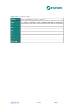
The measurement precision is ±2% precision in a band covering ±20% of Rated Current and ±4%
in the rest of the range of measurements. 16 samples/cycle are taken.
Frequency measurement is obtained by using the passing through zero of the voltage algorithm.
To obtain line frequency and busbar voltage to get busbar frequency it is specifically used phase
B voltage. The minimum value of this voltage to get frequency measurement are 30 volts. If the
voltage of phase B is lower than 30 volts frequency mesuremint will be 0.00 Hz. The frequency
measurement accuracy is ±0.01 Hz.
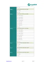
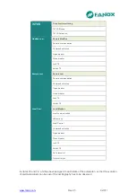
The following measurements are provided:
•
Phase r.m.s. currents (IA, IB, IC)
•
Neutral r.m.s. current (IN)
•
Positive sequence current (I1)
•
Negative sequence current (I2)
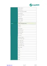
•
Phase r.m.s. voltages (VA, VB, VC)
•
Residual neutral voltage (VN), calculated internally from the sum of the phase
voltages.
•
Busbar phase B r.m.s. voltage (VBBus)
•
Voltage between phases (U12, U23, U31)
•
Angle current phase L1 respect to VL1(ang-IA)
•
Angle current phase L2 respect to VL1(ang-IB)
•
Angle current phase L3 respect to VL1(ang-IC)
•
Total Active Power (P)
•
Phase Active power (P-A, P-B, P-C)
•
Total Reactive Power (Q)
•
Phase Reactive power (Q-A, Q-B, Q-C)
•
Total apparent power (S)
•
Phase Apparent power (S-A, S-B, S-C)
•
Power factor (cos Phi)
•
Each phase Power factor (cos Phi-A, cos Phi-B, cos Phi-C)
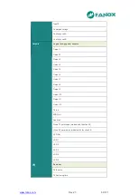
•
Thermal image
•
Line frequency and Busbar frequency
•
Phase difference between phase B line voltage and busbar voltage
Summary of Contents for SIL B
Page 1: ...EN_FANOXTD_MANU_SIL_Feeder_SILB_R023 Docx USER S MANUAL SIL B Feeder Relay...
Page 8: ...www fanox com Rev 23 8 311 2 DIMENSIONS AND CONNECTION DIAGRAMS 2 1 Equipment front view...
Page 9: ...www fanox com Rev 23 9 311 2 2 Equipment dimensions...
Page 10: ...www fanox com Rev 23 10 311...
Page 11: ...www fanox com Rev 23 11 311 2 3 Cut out pattern CUT OUT PATTERN...
Page 12: ...www fanox com Rev 23 12 311 2 4 Connection diagrams Analog connections...
Page 13: ...www fanox com Rev 23 13 311...
Page 14: ...www fanox com Rev 23 14 311 Digital connections Outputs and Trip circuit supervision...
Page 15: ...www fanox com Rev 23 15 311 2 5 Terminals IEC 61850 or DNP3 0 protocols...
Page 17: ...www fanox com Rev 23 17 311 IEC 60870 5 103 protocol...
Page 25: ...www fanox com Rev 23 25 311 3 3 Functional diagram...
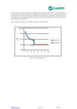
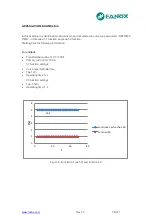
Page 28: ...www fanox com Rev 23 28 311 3 5 1 SIL B 1 CHARGE CURVE 3 5 2 SIL B 5 CHARGE CURVE...
Page 91: ...www fanox com Rev 23 91 311...
Page 140: ...www fanox com Rev 23 140 311...
Page 194: ...www fanox com Rev 23 194 311 Polarization V 35 0 V C Operating Angle 180 C Halfcone Angle 3 C...
Page 307: ...www fanox com Rev 23 307 311 50BF init Fault init 79 Closure permission 52 closure permission...
Page 310: ...www fanox com Rev 23 310 311 NOTES...
Page 311: ...www fanox com Rev 23 311 311...