


Rev.23
43/311
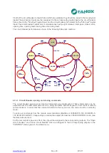
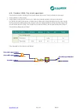
4.12. Function 81O/U. Overfrequency and underfrecuency protection
There are four protection units of the variation in frequency. Each one of them has an adjustment which
determines whether the unit acts as overfrequency or underfrequency. The reaction time of the unit is
determined by the set operating time.
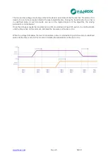
In case the unit acts like overfrequency, activation of the function occurs at 100% frequency level set
and is reset when the measured frequency is 50 mHz lower than set start level.
If the unit is set as underfrequency, activation of the function occurs at 100% frequency level set and is
reset when the measured frequency is 50 mHz higher than set start level.
The reset is temporized and the reset time is determined by the reset time setting.
Accuracy of operating time and reset time is adjusted time plus a maximum of 30ms.
The frequency measurement is done from the voltage of phase B. It takes a minimum of 30 volts at this
stage for 81 functions to be operational. If the measured phase voltage is less than 30 volts, it activates
a state bit indicating function blocked. When the frequency measurement is again valid, function begins
in the start state with all bits and counters reset.
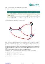
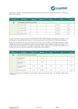
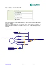
This protection function is adjusted by setting five different parameters:
Function
Description
Minimum
Maximum
Step
Unit
Default
81_1
81_2
81_3
81_4
Overfrequency or Underfrequency
Permission
-
-
Yes/No
-
No
Type
-
-
(1*)
-
Underfrequency
Activation level
45.00
65.00
0.01
Hz
55
Operating time
0.06
300.00
0.01
s
100
Reset time
0.2
1200.0
0,1
s
0.2
(1*) Overfrequency or Underfrequency
Summary of Contents for SIL B
Page 1: ...EN_FANOXTD_MANU_SIL_Feeder_SILB_R023 Docx USER S MANUAL SIL B Feeder Relay...
Page 8: ...www fanox com Rev 23 8 311 2 DIMENSIONS AND CONNECTION DIAGRAMS 2 1 Equipment front view...
Page 9: ...www fanox com Rev 23 9 311 2 2 Equipment dimensions...
Page 10: ...www fanox com Rev 23 10 311...
Page 11: ...www fanox com Rev 23 11 311 2 3 Cut out pattern CUT OUT PATTERN...
Page 12: ...www fanox com Rev 23 12 311 2 4 Connection diagrams Analog connections...
Page 13: ...www fanox com Rev 23 13 311...
Page 14: ...www fanox com Rev 23 14 311 Digital connections Outputs and Trip circuit supervision...
Page 15: ...www fanox com Rev 23 15 311 2 5 Terminals IEC 61850 or DNP3 0 protocols...
Page 17: ...www fanox com Rev 23 17 311 IEC 60870 5 103 protocol...
Page 25: ...www fanox com Rev 23 25 311 3 3 Functional diagram...
Page 28: ...www fanox com Rev 23 28 311 3 5 1 SIL B 1 CHARGE CURVE 3 5 2 SIL B 5 CHARGE CURVE...
Page 91: ...www fanox com Rev 23 91 311...
Page 140: ...www fanox com Rev 23 140 311...
Page 194: ...www fanox com Rev 23 194 311 Polarization V 35 0 V C Operating Angle 180 C Halfcone Angle 3 C...
Page 307: ...www fanox com Rev 23 307 311 50BF init Fault init 79 Closure permission 52 closure permission...
Page 310: ...www fanox com Rev 23 310 311 NOTES...
Page 311: ...www fanox com Rev 23 311 311...