


Rev.23
32/311
4.3.
Functions 50N/G_1 and 50N/G_2. Instantaneous neutral overcurrent
This protection function can be set by using three parameters:
Function
Description
Minimum
Maximum
Step
Unit
Default
50N/G_1
50N/G_2
Neutral instantaneous overcurrent
Permission
-
-
Yes/No
-
No
Tap
0.10
30.00
0.01
I nominal
1.00
Operating
time
0.02
300..00
0.01
s
0.02
The operating time is completely independent from the operating current that flows through the
equipment, so if the neutral current exceeds its predetermined value for an equal or greater amount of
time than this preset value, the protection function activates (trips) and does not reset itself until the
average value of the phase drops below the point of current tap.
The function activates at 100% of the preset input, and deactivates at 95%. The reset is instantaneous.
The accuracy of the operation time is equal to the preset time plus a maximum of 30 ms.
4.4.
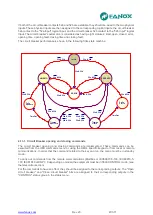
Function 67N1 & 67N2. Inverse-time neutral directional overcurrent
Two neutral directional units are available: 67N1 y 67N2.
This function uses the residual voltage as a polarization magnitude and the residual current as an
operating magnitude. The intervention sector is defined in the following way: the operating angle is
rotated anticlockwise from the residual voltage, which gives us the maximum torque direction. A cone is
drawn, with the half-cone angle adjusted, over this maximum torque direction.
If the directionality option is not activated, the 67N function behaves like a 50/51N/G function.
The actuation time starts when the following conditions are met simultaneously:
•
Residual voltage higher than adjusted
•
Residual current higher than adjusted
•
The phase shift of residual current and residual voltage is such that the residual current is
inside the intervention sector.
Summary of Contents for SIL B
Page 1: ...EN_FANOXTD_MANU_SIL_Feeder_SILB_R023 Docx USER S MANUAL SIL B Feeder Relay...
Page 8: ...www fanox com Rev 23 8 311 2 DIMENSIONS AND CONNECTION DIAGRAMS 2 1 Equipment front view...
Page 9: ...www fanox com Rev 23 9 311 2 2 Equipment dimensions...
Page 10: ...www fanox com Rev 23 10 311...
Page 11: ...www fanox com Rev 23 11 311 2 3 Cut out pattern CUT OUT PATTERN...
Page 12: ...www fanox com Rev 23 12 311 2 4 Connection diagrams Analog connections...
Page 13: ...www fanox com Rev 23 13 311...
Page 14: ...www fanox com Rev 23 14 311 Digital connections Outputs and Trip circuit supervision...
Page 15: ...www fanox com Rev 23 15 311 2 5 Terminals IEC 61850 or DNP3 0 protocols...
Page 17: ...www fanox com Rev 23 17 311 IEC 60870 5 103 protocol...
Page 25: ...www fanox com Rev 23 25 311 3 3 Functional diagram...
Page 28: ...www fanox com Rev 23 28 311 3 5 1 SIL B 1 CHARGE CURVE 3 5 2 SIL B 5 CHARGE CURVE...
Page 91: ...www fanox com Rev 23 91 311...
Page 140: ...www fanox com Rev 23 140 311...
Page 194: ...www fanox com Rev 23 194 311 Polarization V 35 0 V C Operating Angle 180 C Halfcone Angle 3 C...
Page 307: ...www fanox com Rev 23 307 311 50BF init Fault init 79 Closure permission 52 closure permission...
Page 310: ...www fanox com Rev 23 310 311 NOTES...
Page 311: ...www fanox com Rev 23 311 311...