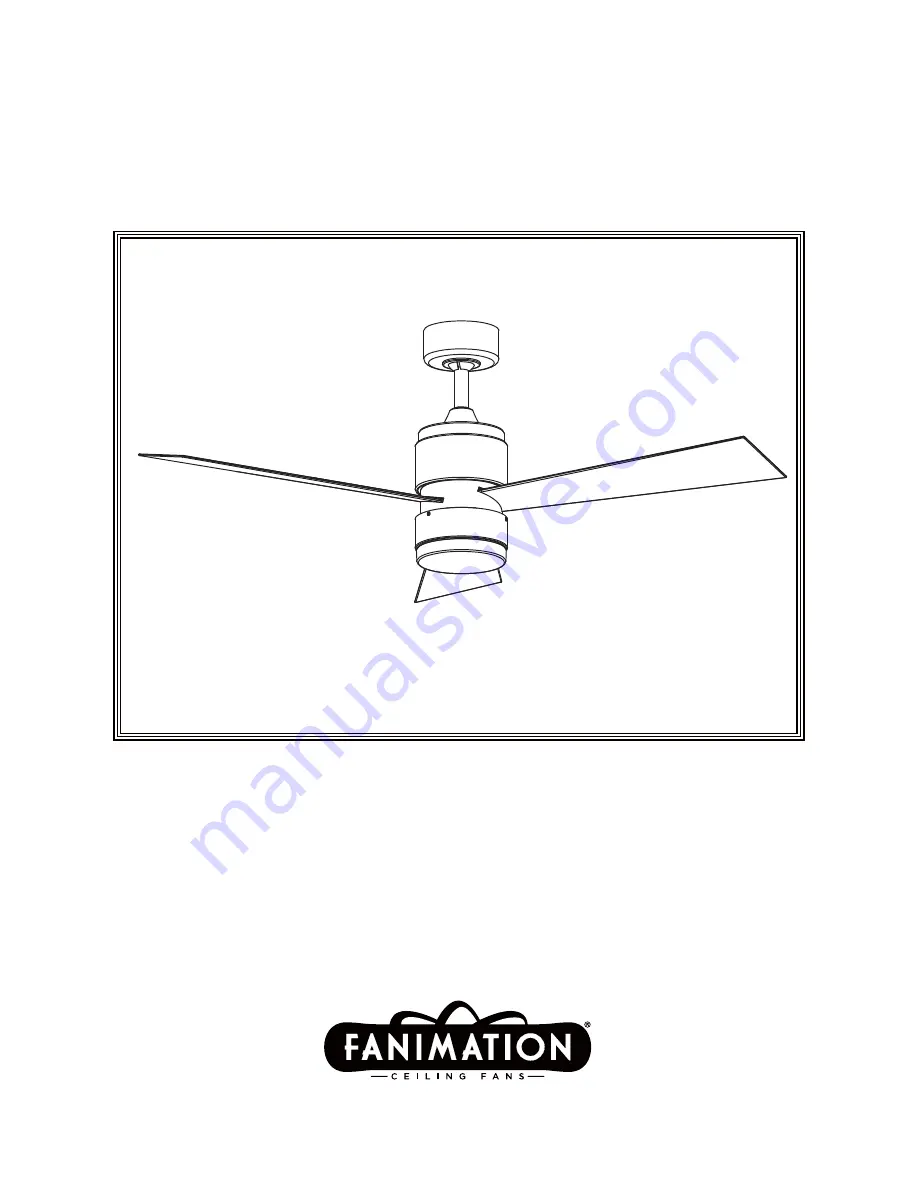
Model No. FP4650**
OWNER'S MANUAL
READ AND SAVE THESE INSTRUCTIONS
The Zonix
™
Ceiling Fan
Net Weight 17.90 lbs (8.12 kg)
Page 1: ...Model No FP4650 OWNER S MANUAL READ AND SAVE THESE INSTRUCTIONS The Zonix Ceiling Fan Net Weight 17 90 lbs 8 12 kg ...
Page 2: ...als or workmanship labor to repair the motor will be provided free of charge at our national service center Purchaser will be responsible for labor charges after this one year period Customer shall be responsible for all costs incurred in the removal or reinstallation and shipping of the product for repairs or replacement 3 If any other part of your fan fails at any time within one year after orig...
Page 3: ...d a problem or a defect Unpacking Instructions 4 Energy Efficient Use of Ceiling Fans 5 Electrical and Structural Requirements 5 How to Assemble Your Ceiling Fan 7 How to Hang Your Ceiling Fan 9 How to Wire Your Ceiling Fan 10 How to Install Your Canopy Housing 11 How to Assemble the Light Kit 12 How to Operate Your Ceiling Fan 13 Maintenance 14 How to Clean Your Ceiling Fan Blades 14 How to Insta...
Page 4: ...y ardware Eags 7en Ý asher and 6crews with iEer ashers 3hillips 6crewdriver Ý our ire Connectors alance it Hanger Bracket Assembly Receiver Glass Unit Fan Motor Assembly Hardware Bag Blade Set Hand Held Remote Control Canopy Screw Cover Assembly This manual is designed to make it as easy as possible for you to assemble install operate and maintain your ceiling fan Tools Needed for Assembly One Phi...
Page 5: ...es warm air near the ceiling down into the occupied space Remember to adjust your thermostat when using your ceiling fan additional energy and dollar savings could be realized with this simple step Electrical and Structural Requirements Your new ceiling fan will require a grounded electrical supply line of 120 volts AC 60 HZ 15 Amp Circuit Electrical code requires use of a fan rated outlet box to ...
Page 6: ...box marked acceptable for fan support of 15 88 kg 35 lbs or less Use screws supplied with outlet box Most outlet boxes commonly used for support of light fixtures are not acceptable for fan support and may need to be replaced Consult a qualified electrician if in doubt WARNING No blocking Figure 3 Paired with a deep box this hanger is meant to span between two joists and takes the place of wooden ...
Page 7: ...wnrod support on top of the motor Install the clevis pin by aligning the holes in the downrod support with holes in the downrod Secure clevis pin with hairpin clip Tighten the two set screws with nuts in the downrod support Figure 4 WARNING It is critical that the clevis pin in the downrod support is properly installed and the set screws and nuts are securely tightened Failure to do so could resul...
Page 8: ...ed where necessary before installation Figure 6 6 Reinstall the hanger ball on the downrod as follows Route the three 80 in wires through the hanger ball Position the pin through the two holes in the downrod and align the hanger ball so the pin is captured in the groove in the top of the hanger ball Pull the hanger ball up tight against the pin Securely tighten the set screw in the hanger ball A l...
Page 9: ... The outlet box must be securely anchored Hanger bracket must seat firmly against outlet box If the outlet box is recessed remove wall board until bracket contacts box If bracket and or outlet box are not securely attached the fan could wobble or fall WARNING 2 Carefully lift the fan and seat the downrod hanger ball assembly on the hanger bracket that was just attached to the outlet box Be sure th...
Page 10: ...tting is all up Do not use this position With a small screwdriver or ball point pen slide firmly up or down Replace battery cover on the transmitter Figure 2 2 To set the receiver unit code slide code switches to the same positions as set on your transmitter Figure 3 3 Slide the receiver unit into the open end of the hanger bracket Figure 4 4 Connect green wires from hanger bracket and hanger ball...
Page 11: ...lly assemble and tighten second shoulder screw that was previously removed Figure 1 WARNING To avoid possible fire or shock make sure that the electrical wires are completely inside the canopy housing and not pinched between the housing and the ceiling NOTE This step is applicable after the neccessary wiring is completed Figure 1 Ceiling Canopy Figure 1 Canopy Screw Cover Figure 2 INSTALLATION NOT...
Page 12: ...previously removed screws Figure 4 5 Secure the glass to light kit assembly by twisting in a clockwise direction Do not over tighten Figure 5 2 Remove one of the four screws in the support bracket at the bottom of the motor assembly Slightly loosen the remaining three screws Assemble the support cover switch cup to the support bracket using the three key slots in the support cover switch cup Repla...
Page 13: ...nformation Season Rotation Direction Switch Position Summer Counter Clockwise Left Winter Clockwise Right 3 To make fan operational install two 3 volt batteries included in the hand held remote transmitter If not using for long periods of time remove battery to prevent damage to transmitter Store the remote away from excessive heat or humidity Figure 3 MAIN FUSE BOX Figure 1 Figure 2 Figure 3 REMO...
Page 14: ... How to Install Your Remote Control Option 1 How to Install Your Remote Control Option 2 How to Install Your Remote Control Option 3 1 Drill the two 1 4 holes in wall and use the M6 plastic anchor pushed into the holes Install the control bracket with two 3 1 self tap screws Push the four plastic plug to cover the screw holes Including in the control Figure 1 1 Unthread two screws from the wall sw...
Page 15: ...o fan 2 Loose screws in motor housing 4 Wire connectors inside housing rattling 5 Motor noise caused by solid state variable speed control 6 Screws holding blades to blade holders are loose 3 FAN WOBBLES EXCESSIVELY 1 Tighten both setscrews securely in downrod support 2 Tighten the setscrew in the downrod hanger ball assembly 3 Check to be sure screws which attach the fan blade holders to the blad...
Page 16: ...er 4Ý 3 16Ý 24 Washer Head Screws with Fiber Washers 10 Loose Hardware Bag Blade Mounting Hardware Bag HOW TO ORDER REPAIR PARTS When ordering repair parts always give the following information Part Number Part Description Fan Model Number Contact your retail store for repair parts Before discarding packaging material be certain all parts have been removed Insert FINISH CODES Refer to fan model nu...
Page 17: ...ploded View Illustration NOTE The illustration shown is not to scale or its actual con guration may vary Product parts are subject to change without notice Figure 1 The Zonix 13 11 13 7 8 10 1 2 3 4 5 6 9 12 10a 10b 10c ...
Page 18: ......
Page 19: ...Copyright 2015 Fanimation 2015 08 V 01 10983 Bennett Parkway Zionsville IN 46077 888 567 2055 FAX 866 482 5215 Outside U S call 317 733 4113 Visit Our Website www fanimation com ...
Page 20: ...The Zonix Ventilador de techo Peso neto 8 12 kg 17 90 lbs Modelo N º FP4650 MANUAL DEL PROPIETARIO LEA Y GUARDE ESTAS INSTRUCCIONES ...
Page 21: ... ésta debe ser capaz de soportar sin problemas al menos 15 9 kg 35 lb Consulte la página 3 21 del manual del propietario para ver los requisitos de soporte Si tiene dudas consulte a un electricista calificado Las aspas del ventilador deben instalarse por lo menos a 2 13 m 7 pies del suelo a fin de evitar un contacto accidental con las mismas 4 Siga las recomendaciones sobre el método correcto de i...
Page 22: ...obre las garantías implícitas Fanimation no se hará responsable por daños accidentales resultantes o especiales derivados del uso o el rendimiento del producto o en conjunción con éste excepto en los casos en los que la ley así lo disponga Esta garantía le otorga derechos legales especiales y es posible que también goce de otros derechos que pueden variar según el estado Es normal que se produzca ...
Page 23: ...l tipo requerido por el código local El cable más pequeño debe ser un cable de tres conductores de dos conductores con conexión a tierra del siguiente tamaño NOTA coloque las piezas de las bolsas de piezas individuales en un contenedor pequeño para evitar que se extravíen Si faltan piezas pón gase en contacto con su proveedor local Materiales tamaño del cable según el A W G Calibre de Alambre Esta...
Page 24: ...ectainstalación yuso Acontinuaciónlepresentamosalgunassugerencias para asegurar un rendimiento eficiente del producto Selección del lugar de montaje adecuado Los ventiladores de techo se deben instalar en el centro de la habitación a 2 13 m 7 pies de altura del piso como mínimo y 0 5 m 18 pulgadas de las paredes Si la altura del techo lo permite instale el ventilador a 2 5 m 8 9 pies por encima de...
Page 25: ...e que la electricidad esté desconectada en la caja de fusibles principal antes de realizar la instalación eléctrica Toda instalación eléctrica debe cumplir con los códigos nacionales y locales y el ventilador de techo debe tener la conexión a tierra adecuada como forma de precaución ante posibles descargas eléctricas ADVERTENCIA Para reducir el riesgo de incendios descargas eléctricas o lesiones p...
Page 26: ...tale la clavija de horquilla y asegúrela con la pinza de horquilla Fije los dos tornillos de presión y las tuercas de seguridad en el soporte de la varilla interior Figura 4 Es fundamental que instale correctamente el pasador de horquilla en el soporte de la varilla y que ajuste firmemente los tornillos de fijación y las tuercas El incumplimiento de dicho paso podría hacer que el ventilador se cai...
Page 27: ...de la parte superior de la misma Empuje la semiesfera hacia arriba bien ajustada contra el pasador Ajuste firmemente el tornillo de fijación en la semiesfera Si el tornillo de fijación está flojo podría provocar oscilación del ventilador Figura 6 8 Corte el exceso de cable aproximadamente de 15 a 23 cm 6 a 9 pulgadas por encima de la parte en cada extremo del cable Figura 7 NOTA Se deben revisar t...
Page 28: ... de salida no están bien aseguradas el ventilador podría tambalearse o caerse Si no coloca la lengüeta en la ranura podrían dañarse los cables eléctricos y podrían ocurrir incendios o descargas eléctricas ADVERTENCIA ADVERTENCIA ADVERTENCIA Para evitar una posible descarga eléctrica no apriete los cables entre el ensamble de la bola para colgar y la abrazadera para colgar ADVERTENCIA NOTA Si no es...
Page 29: ...ceptor marcado AC IN L al cable negro de suministro de electricidad utilizando el conector de cables suministrado Conecte el cable blanco desde la unidad del receptor marcado AC IN N al cable blanco de suministro de electricidad utilizando el conector de cables suministrado Conecte el cable blanco desde la unidad del receptor marcado TO MOTOR N al cable blanco del ventilador utilizando el conector...
Page 30: ...letamente empujarse con cuidado en el cuadro de juntura y de que no estén aprisio el techo ADVERTENCIA NOTA Este paso se debe realizar luego de completar la completed instalación eléctrica necesaria Cubierta de unión del motor Cubierta para el tornillo del capuchón NOTA DE INSTALACIÓN No conecte las aspas hasta que el ventilador esté totalmente instalado Instalar el ventilador con las aspas coloca...
Page 31: ...orte utilizando las dos ranuras principales de cubierta del interruptor de la carcasa de soporte Vuelva a colocar el cuarto tornillo y asegure los cuatro tornillos Figura 2 A fin de reducir el riesgo descargas eléctricas desconecte el circuito de suministro eléctrico al ventilador antes de instalar el kit de iluminación PRECAUCIÓN 3 Instale el conector de 2 clavijas desde la kit de iluminación con...
Page 32: ...l mismo Se dispone de niveles de luces infinitos manteniendo pulsado el botón on off Figura 4 Información sobre el interruptor de reversa Temporada Verano Invierno Dirección de rotación En dirección de las manecillasdel reloj En dirección contraria a las manecillas del reloj Derecha Izquierda Posición del interruptor Si se desea que el flujo del aire vaya en la dirección opuesta apague el ventilad...
Page 33: ...ómo instalar su mando a distancia Opción 1 1 Retire los dos tornillos colocados en la plaza del interruptor de la pared Figura 1 2 Instale el soporte de control con los dos tornillos 6 32x 3 4 Empuje los cuatro tapones de plástico para cubrir los orificios de los tornillos Incluidos con el mando Figura 2 Cómo instalar su mando a distancia Opción 2 1 Retire los dos tornillos colocados en la plaza d...
Page 34: ...ministro principal de electricidad esté desconectado 5 Algunos motores de ventilador son sensibles a las señales de los controles de velocidad de estado sólido variables Los controles de estado sólido no son recomendables Escoja un método de control alternativo 6 Ajuste bien los tornillos 3 EL VENTILADOR OSCILA EN EXCESO 1 El tornillo de fijación y la tuerca del soporte de barral están flojos 2 El...
Page 35: ...ner las piezas de repuesto 35 Modelos N FP4650 Lista de piezas Conectores de cables 4 Kit de balanceo Destornillador Phillips de 4Ý Bolsa de accesorios Bolsa de accesorios para el montaje de aspas Tornillos con cabeza de arandela de 3 16Ý 24 con arandelas de fibra 10 or Unidad del soporte de suspensión Cubierta para el tornillo del capuchón Unidad del barral de la semiesfera Capuchón de techo Cubi...
Page 36: ...13 11 13 7 8 10 1 2 3 4 5 6 9 12 10a 10b 10c 36 Figura 1 The Zonix Modelo FP4650 Despiece NOTA la ilustración que se muestra no está hecha a ...
Page 37: ......
Page 38: ...015 Fanimation 2015 08 V 01 10983 Bennett Parkway Zionsville IN 46077 Llame sin cargo al 888 567 2055 FAX 866 482 5215 Desde fuera de los EE UU llame al 317 733 4113 Visite nuestro sitio Web en www fanimation com ...