


24
INSTALLATION
Check the appliance is electrically safe when you have finished.
ArtNo.070-0014 - Stability bracket - Wall fitting
Cooker
Stability bracket
Floor
3 mm min
Typical floor mounting
Cooker
Outer stability
bracket
Floor
Wall
3 mm min
Typical wall mounting
Fig. 8.5
Fig. 8.6
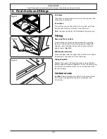
Repositioning the cooker following
connection
If you need to move the cooker once it has been connected,
make sure it is switched off at the supply switch before
gripping under the fascia panel and lifting the front of the
cooker slightly (Fig. 8.3). Check behind the cooker to make
sure that the electricity cable is not caught. As you progress,
always make sure that the cable has sufficient slack to allow
the cooker to move.
When you replace the cooker, check behind it again once
more to make sure that the electricity cable is not caught or
trapped.
Levelling
You are recommended to use a spirit level on a shelf in one of
the ovens to check for level.
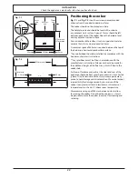
Place the cooker in its intended position, taking care not to
twist it within the gap between the kitchen units as damage
may occur to the cooker or the units.
The front feet and rear rollers can be adjusted to level the
cooker.
To adjust the height of the rear of the cooker use a 13 mm
spanner or socket wrench to turn the adjusting nuts at the
front bottom corners of the cooker.
To set the front, turn the feet bases to raise or lower.
Fitting the stability bracket
Suitable stability devices are shown in Fig. 8.5 and Fig. 8.6.
Adjust the bracket to give the smallest practicable clearance
between the bracket and the engagement slot in the rear of
the cooker.
Fit the bracket so that it engages as far as possible over the
chassis of the cooker.
Typical floor mounting
Typical wall mounting
Summary of Contents for 1092 Continental Induction G5
Page 1: ...U110267 04 Falcon 900s Induction USER GUIDE INSTALLATION INSTRUCTIONS ...
Page 4: ...ii ...
Page 39: ...35 Notes ...