background image

Page

Chapter: 4

Section:

DRO MODE OF OPERATION

6

N

7

6

5

I

K

4

3

2

1

A

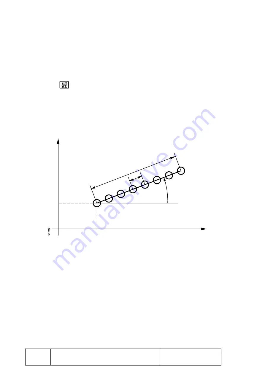
4.1.2   DRILLING IN A LINEAR PATTERN

The linear drilling operation can be carried out either in absolute or incremental
modes.

Follow these steps to select this function:

*

Press

 and select “SPECIAL FUNCTIONS”.

*

Select “DRILLING IN LINE”.

Indicate the two axes which form the main axes where the drilling will be carried out.

The following parameters must be defined in order to perform a linear drilling
operation:

1st and 2nd axes Define the coordinates of the first drilling point in ABS or INC.

If none of these two parameters are defined, the DRO will take a value of 0.

A

Defines the angle formed by the drilling path (line) and the abscissa axis
(horizontal). It is given in degrees and if no value is programmed, the DRO will
take a value of 0.

I

Defines the distance between holes.

If a value is assigned to this parameter, no value must be assigned to “K”.

1st Axis

2nd Axis

DRILLING IN A LINEAR

PATTERN

Summary of Contents for VNP400

Page 1: ...FAGOR VNP400 Ref 9506 in...

Page 2: ...FAGOR AUTOMATION S Coop Ltda reserves the right to modify the contents of this manual without previous notification...

Page 3: ...terface 2 2 2 1 General considerations 2 2 3 Set up 4 2 3 1 General considerations 4 2 3 2 Connection 4 2 4 Reference systems 5 2 4 1 Absolute and incremental coordinates 5 2 5 Start up 6 2 6 Home sea...

Page 4: ...4 5 Clock function 20 5 PROGRAMEDITING 5 1 Introduction 1 5 2 Program editing 2 5 2 1 Block editing 4 5 2 2 Contents of a block 6 5 3 TEACH INprogramming 8 6 PROGRAMEXECUTION 6 1 Introduction 1 6 2 O...

Page 5: ...havingonitsfrontpanel A CRT monitor used to display the required system information A keyboard to communicate with the DRO in order to request information by means of commands or alter the status of t...

Page 6: ...Page Chapter 1 Section CONFIGURATIONOFTHEDROMODELVNP400 2 Rear panel of the VNP400 STRUCTUREOFTHEVNP400...

Page 7: ...DRO is a table top model and it should be installed so the operator s eyes are aligned with the DRO monitor It has four legs screwed on to the bottom with a 5mm inside thread in order to be fastened...

Page 8: ...essary information 2 This display area shows the different options which can be selected by means of softkeys F1 thru F5 The keyboard area which allows communications with the DRO consists of the foll...

Page 9: ...s Cancels the last character sequence entered Used to validate commands and data previously altered or generated Cancels the last character entered It is used to enter a position value directly when i...

Page 10: ...s X5 9 pin female SUB D type connector for the RS 232C and probe connection 1 Lithium battery for memory back up when the DRO power is off 2 Identification label of the VNP400 3 Two3 15A 250VfusesforA...

Page 11: ...ctor admitting either square or sine wave signals Thetypeofcableusedmustbeshielded therestofthecharacteristicsaswellastheirlengths will depend on the type of feedback device being used It is recommend...

Page 12: ...ncebetween130and170pF meter the maximum cable length must not exceed 15 meters 50 feet Itisrecommendedtouseshieldedtwisted paircablesinordertominimizeinterference which could cause poor quality commun...

Page 13: ...EDROMODELVNP400 9 RECOMMENDED CONNECTIONS FOR THE RS 232C INTERFACE Complete connection HOUSING 1 FG 2 TxD 3 RxD 4 RTS 5 CTS 6 DSR 20 DTR 7 GND FG 1 TxD 2 RxD 3 RTS 4 CTS 5 DSR 6 DTR 9 GND 7 PERIPHERA...

Page 14: ...not have RTS signal If the unit receiving data can receive it at the selected baudrate Nevertheless thetechnicalmanualsofthecomputerorperipheralshouldbeconsulted for any possible discrepancies Whenusi...

Page 15: ...ws etc whenever possible It is recommended to keep the DRO away from any device generating a strong magnetic field which could cause undesirable image fluctuations on the monitor 2 1 POWER CONNECTION...

Page 16: ...l in order to achieve The protection of people against electrical discharges caused by any malfunction Theprotectionofelectronicequipmentagainstinterferencegeneratedatthemachine itselforbyotherelectro...

Page 17: ...Thisgroundingofthe shield is done at the DRO s ground terminal Eachelementofthemachine tool DROinstallationmustbeconnectedtogroundthrough the established main ground points They will be conveniently s...

Page 18: ...binetisdisconnected from the A C power ThisconnectionmustbedoneonasinglemachinepointcalledMainGroundPointtowhich allothergroundpointsfromthemachineandfromtheelectricalcabinetwillbeconnected Verify tha...

Page 19: ...l coordinates ItispossibletoassociateanincrementalZeropointtoeachoneofthe9absolutezeros set previously plus another one for the Machine Reference Zero home OncethedesiredPartZerosandFloatingzeroshaveb...

Page 20: ...e DRO performs an initial self test and depending on the result the DRO will act the following way If the self test is successful the DRO will display the following screen If the self test is not succ...

Page 21: ...ive reference point Up to 10 absolute and incremental reference points are available REF 0 thru REF 9 TOOL n Indicates the number of the active tool Adisplayareawheretheotherabsoluteorincrementalposit...

Page 22: ...count Once the corresponding key is pressed it is possible to select the type of tool compensation to be applied and its sign by using the and keys CHANGE TOOL Used to select a new tool After pressing...

Page 23: ...int home 3 Indicates the current axis position 4 Indicatesthepositionoftheactive currentlyselected partzeroorabsolutezero point This symbol will only appear when working in absolute coordinates 5 Indi...

Page 24: ...following options to select one of the shown functions Press the key corresponding to the number associated to the desired function Use the and to move the cursor and when the desired option is highli...

Page 25: ...steps to perform a home search The DRO must not display any menu windows superimposed on the screen If this is not the case press Also REF 0 must be selected If not select it by using CHANGE REFERENCE...

Page 26: ...ehomeisfound theDROwillrecovertheabsoluteandincrementalzeroscorresponding to each reference REF 0 thru REF 9 when recalled Note It is recommended to perform a home search after power up especially whe...

Page 27: ...redtothecorrespondingabsolutezero offset and the incremental position values to the incremental zero offset To set any of these zero offsets follow these steps The DRO must not display any window supe...

Page 28: ...esetting operation when started press the softkey corresponding to that axis The DRO will recover the position value it previously had Press The DRO assumes the new value as the new position value for...

Page 29: ...ANDPOWERCONNECTION PARTZERO HOME WhenpresettingaPartZero theFloatingzerocorrespondingtothatreferenceisalso modified in such a way the distance between both zeros is kept the same FLOATING ZERO FLOATIN...

Page 30: ...ensationtablewillindicate the two tool dimensions in length Follow these steps to apply tool compensation to a linear axis The DRO must not display any menu windows superimposed on the screen If this...

Page 31: ...d corresponding to the selectedtool To cancel the definition of a tool compensation press Press The DRO assumes the selected type of tool compensation for that axis and it will display next to the axi...

Page 32: ...following situations may occur a The problem is now observed in the display window corresponding to the other axis which counted right before Thismeansthatthefeedbackdevice linearscale readerhead rot...

Page 33: ...back being used the counting direction the display resolution leadscrew errors to be compensated etc These values may be introduced by hand from the keyboard or from a peripheral device via the option...

Page 34: ...the right of the CRT can be selected by using softkeys F1 thru F5 and they are the following HOME This option is displayed when there are more than one parameter table It gives access to the first pa...

Page 35: ...the internal parameter table with the new values It keeps the old ones The DRO will display again the available options to operate with the machine parameters When pressing the key the DRO exits the p...

Page 36: ...llimeters or inches for the axes shown on power up P003 Defines the type of probe signal flank being used Probe not being used Up flank level change from 0V to Vcc Down flank level change from Vcc a 0...

Page 37: ...of stop bits used at the end of the transmitted word 1 1 STOP bit 2 2 STOP bits P008 Indicates the type of parity used in the RS 232C communications No parity used Even parity Odd parity P009 Indicat...

Page 38: ...he key is inhibited By pressing the DRO will return the data control to the keyboard modifying the setting of this machine parameter P012 Indicates whether the machine parameters for the axes are lock...

Page 39: ...iated with the corresponding axis It may consist of a letter or a letter with a subindex For example A AB X X0 etc The possible characters to be used are shown in a window and they can be selected by...

Page 40: ...s the name of the first axis P101 ADD Display the addition of the two axes P102 1 1st operand P103 3 2nd operand Px04 Indicates whether the reading of this axis will be displayed or not on the CRT YES...

Page 41: ...x11 Indicates the multiplying factor x5 x10 x20 or x25 that the DRO will apply besides the one indicated in Px10 to the sinewave feedbacksignalsfromthisaxis Px12 Indicates the feedback counting resolu...

Page 42: ...a 10 m pitch will be used Grading pitch 10 m Px05 SINEWAVE Px06 LINEAR Px07 MM DEG Px10 x4 Px11 x25 Px12 0 0001 Example 3 To obtain a 0 0002 resolution with 5 turns inch 0 2 inch turn leadscrew and sq...

Page 43: ...n the multiplying factor to be applied will be 360 degrees 360 degrees Factor 100 nr of pulses x Resolution 3600 x 0 001 degrees Px05 SINEWAVE Px06 ROTARY Px07 MM DEG Px10 x4 Px11 x25 Px12 0 001 Px13...

Page 44: ...Indicates the upper travel limit that the axis can reach when executing a part It will be referred to Machine Reference Zero home This position must be given with the display resolution selected in ma...

Page 45: ...d and it must have an error value of 0 assigned to it The maximum error slope between two consecutive error values must not be greater than 7 For example The maximum error difference between two conse...

Page 46: ...s PARAMETER RESET is carried out when due to an error there is partial or total loss of data Nevertheless and in order to avoid unwanted parameter resets the DRO will ask for confirmation when selecti...

Page 47: ...POSITIVE P109 YES P209 YES P309 YES P409 NO P110 x4 P210 x4 P310 x4 P410 x4 P111 x5 P211 x5 P311 x5 P411 x5 P112 0 0050 P212 0 0050 P312 0 0050 P412 0 0050 P113 0 0050 P213 0 0050 P313 0 0050 P413 0 0...

Page 48: ...EG for example 6 4370 or in degrees minutes and seconds DMS for example 6 23 13 depending on the highlighted text in the corresponding lower window Press the key to toggle between the two types of dis...

Page 49: ...emental or absolute the DRO will display the following values INCH MM REF ABS INC Value Type of coordinate MM MM MM MM REF 0 REF 0 REF 1 REF 1 ABS INC ABS INC 15 7810 8 3800 5 0000 3 5000 To Machine Z...

Page 50: ...the calculation of the part s center using the tool itself and without the need for accessories specially designed for this operation DRILLING IN LINE Once defined the path and the required parameter...

Page 51: ...e steps Press and select SPECIAL FUNCTIONS Select PART CENTER CALC Indicate the two axis forming the main plane where to center the part To perform the part centering operation follow these steps Touc...

Page 52: ...Chapter 4 Section Page DROMODEOFOPERATION 5 X Y Z Press the EXIT softkey to cancel this operation any time Example PARTCENTERING...

Page 53: ...out The following parameters must be defined in order to perform a linear drilling operation 1st and 2nd axes Define the coordinates of the first drilling point in ABS or INC If none of these two par...

Page 54: ...dard display will appear once the program is generated The EXEC function permits to execute the programmed linear drilling as follows 1 The DRO will display the current position with respect to the po...

Page 55: ...ters must be defined in order to perform a this drilling operation 1st and 2nd axes Define the coordinates of the first drilling point in ABS or INC If none of these two parameters are defined the DRO...

Page 56: ...tandard display will appear once the program is generated The EXEC function permits to execute the programmed bolt hole pattern drilling as follows 1 The DRO will display the current position with res...

Page 57: ...e model DRO by means of machine parameter P001 LATHE CONE CALCULATION It calculates the characteristics of a conic part RPM CALCULATION It calculates the revolutions per minute required to obtain a pr...

Page 58: ...ULATION Indicate the two axes which form the main axes where the cone calculation will be carried Out It is required to know two profile points Follow these steps to get those two points Touch one of...

Page 59: ...with each one of the axes of the main plane These angles will be displayed in degrees with a resolution of 0 0001 degree units for example 6 4370 or in degrees minutes and seconds for example 6 23 13...

Page 60: ...INC where the calculation will take place In order to obtain the correct results it is necessary that the Part Zero or Floating Zero coincide with the part s center line This way the value entered he...

Page 61: ...st be unassigned and the V value will have to be defined Press the EXIT softkey to quit this mode during or after this operation When pressing the CALC softkey the DRO will calculate the value of the...

Page 62: ...and LENGTH fields of the tool table corresponding to each tool Tool compensation will only be applied on to the selected axes according to the indicated field RADIUS or LENGTH and with the correspondi...

Page 63: ...The selected option will appear highlighted To choose another tool or field use the and keys The and keys can be used to scroll the information up and down page by page The functions appearing to the...

Page 64: ...ble information assigning a Value of 0 to all the fields of the 99 possible tools The steps to do so are the following Press and select the PROGRAMMING option Select the CLEAR TOOL TABLE option In ord...

Page 65: ...from the keyboard This figure can have a sign and up to 6 decimals The key can be used to delete the last digit entered by mistake 2 Select the desired operation pressing its corresponding softkey The...

Page 66: ...ns memory area and entering a 0 in the data entry area The DRO stores the result of the last operation in its internal memory so it can be recalled for the next calculator operation or when presetting...

Page 67: ...To reset the clock 00 00 00 PRESET To preset the clock with the desired time The DRO will request the desired time Key it in from the keyboard and press ON OFFTo display or not the clock in the upper...

Page 68: ...GRAMS option Prepare the receptor unit before selecting the type of transmission Press the RECEIVE or SEND softkey accordingly RECEIVE to receive the part programs from a computer or peripheral device...

Page 69: ...its contents Before pressing this softkey select the desired program by using the and keys DELETE Used to delete the program highlighted in the part program directory Before pressing this softkey sel...

Page 70: ...cate that incremental coordinate values will be assumed instead P Indicates that the program is protected so it cannot be modified It can however be viewed and executed Use the and keys to select the...

Page 71: ...means of softkeys F1 thru F5 EDIT BLOCK Used to access the selected block bottom of the screen in order to view it or edit its contents To select another block use the keys DELETE BLOCK Deletes the se...

Page 72: ...ndicating the number corresponding to the last selected tool If another tool is desired enter the new number and press Press EXIT to exit this function without modifying it Only a new tool assigned to...

Page 73: ...s by axis highlighting the values of the selected axis Use the keys to select another axis Only the position value and the type of tool compensation can be assigned to each axis After entering the des...

Page 74: ...f tool compensation does not affect that axis an empty area will be displayed instead Use the to select the type of tool compensation No tool compensation Radius Compensation R Length Compensation L A...

Page 75: ...gram number to be entered This number may have up to 5 digits After pressing the DRO will show the positions of all the axes of the machine The procedure to enter the position values of the different...

Page 76: ...m stored in memory which is to be executed If the program does not exist the DRO will display the corresponding message TheactivereferencepointaswellasthedisplayformatINCH MMorDEG DMSmustbe selected b...

Page 77: ...splay the number of the new tool in the lower right hand side window TOOL After changing the tool press the NEXT softkey 3 TheDROwilldisplaythecurrentpositionwithrespecttothepointprogrammedinthe block...

Page 78: ...Indicates the number of stop bits used at the end of each transmitted word P008 Indicates the type of parity check used in the communication P009 Indicates the communication baudrate P010 Indicates t...

Page 79: ...ommunication Once the transmission is completed other programs can be sent or received by pressing RECEIVE or SEND accordingly Press EXIT to quit the transmission mode and the DRO will display the opt...

Page 80: ...nsist of a sign up to 5 digits to the left of the decimal point 4 in inches the decimal point and up to 4 decimals 5 in inches Examples X 12345 1234 AC 1 2300 Z 12 0000 in mm If tool compensation has...

Page 81: ...missions can be performed by pressing RECEIVE or SEND accordingly Press EXIT to quit the transmission mode and the DRO will display the options corresponding to COMMUNICATIONS The elements of the tabl...

Page 82: ...End of text character The DRO uses EOT ASCII 4 as end of text character Example T01 R 5 000 L 12 500 CR First tool T02 R 3 000 L 17 230 CR T98 R 0 000 L 0 000 CR T99 R 0 000 L 0 000 CR Last tool EOT E...

Page 83: ...SEND accordingly Press EXIT to quit the transmission mode and the DRO will display the options corresponding to COMMUNICATIONS It is not necessary to transmit those parameters which have no meaning Fo...

Page 84: ...he letter or letters associated to it Examples P100 X P200 YA P300 Z1 Parameters associated to position values This type of parameters are the ones associated to the display or feedback resolution the...

Page 85: ...ht and by rows The number 1 corresponds to the first option For example if P111 multiplying factor for sine wave feedback signal shows the following options P111 Sinewave Mult x5 x10 x20 x25 The corre...

Page 86: ...diameters DEG DMS mm inches etc If the general machine parameter P004 is set to STOPPED the DRO will freeze the display at the X Y Z position value corresponding to the touch point for as long as the...

Page 87: ...ERISTICS OF FEEDBACK INPUTS Power consumption of 5V 1A 250 mA for each connector Power consumption of 5V 0 4A 100 mA for each connector Work levels for square wave signals Maximum frequency 250KHz Max...

Page 88: ...utput signals 1 5KV maximum Protection against electrostatic discharges meets IEC 801 2 15KV standard BATTERY 3 5Vlithiumbattery Estimated life span 10 years From the moment the low battery message ap...

Page 89: ...by the probe DIRECT CONNECTION Probe with output as normally open contact Probe with output as normally closed contact INTERFACE CONNECTION Interface with open collector output Interface with output i...

Page 90: ...ED or it keeps updating it CONTI NUES P005 Indicatesthetypeofcommunicationsprotocoltobeusedwithacomputerorperipheral device P006 Indicates the number of data bits per character transmitted via RS232 C...

Page 91: ...pulses MM DEG INCHES DMS Px08 Indicates the counting direction Positive or negative Px09 IndicateswhetherthepositionvaluescanbedisplayedornotinRadiusandDiameters Px10 Indicates the multiplication fac...

Page 92: ...7 APPENDIX D MACHINE PARAMETER SETTING CHART GENERAL PARAMETERS MACHINE PARAMETER VALUE P000 P001 P002 P003 P004 P005 P006 P007 P008 P009 P010 P011 P012...

Page 93: ...XES MACHINE PARAMETER VALUE P100 P101 P102 P103 P104 P105 P106 P107 P108 P109 P110 P111 P112 P113 P114 P115 P116 MACHINE PARAMETER VALUE P200 P201 P202 P203 P204 P205 P206 P207 P208 P209 P210 P211 P21...

Page 94: ...PARAMETER VALUE P300 P301 P302 P303 P304 P305 P306 P307 P308 P309 P310 P311 P312 P313 P314 P315 P316 MACHINE PARAMETER VALUE P400 P401 P402 P403 P404 P405 P406 P407 P408 P409 P410 P411 P412 P413 P414...

Page 95: ...10 MACHINE PARAMETER POSITION ERROR P117 P118 P119 P120 P121 P122 P123 P124 P125 P126 MACHINE PARAMETER POSITION ERROR P217 P218 P219 P220 P221 P222 P223 P224 P225 P226...

Page 96: ...11 MACHINE PARAMETER POSITION ERROR P317 P318 P319 P320 P321 P322 P323 P324 P325 P326 MACHINE PARAMETER POSITION ERROR P417 P418 P419 P420 P421 P422 P423 P424 P425 P426...

Page 97: ...rs Re enter the appropriate values PARAMETER ERROR AXIS 1 PARAMETER ERROR AXIS 2 PARAMETER ERROR AXIS 3 PARAMETER ERROR AXIS 4 It occurs when detecting a malfunction at the machine parameters for the...

Page 98: ...oes not supply the proper voltage Replace it and check the machine parameters and part programs since the error may have alteredtheircontents TEMPERATURE ERROR ItoccurswhentheinternaltemperatureoftheD...

Page 99: ...date It covers parts and labor at FAGOR AUTOMATION Travel expenses are payable by the customer Damages due to causes external to FAGOR AUTOMATION such as unauthorized manipulation blows etc are not c...

Reviews: