background image

FabiaTech Corporation 


45 

¾


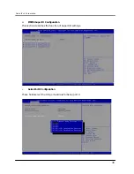
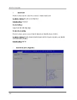
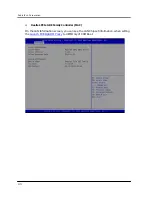
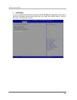
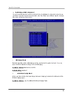
ISA IO Decode Space  

This option allows you to select the IO port space for add on card on FB2701. 


—


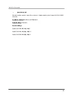
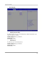
Decode I/O Space 0~5 

These fields are used for the enable configuration and the positive decode IO Space. 

Available Options: Disabled and Enable 

Default setting: Disable  

—


Decode I/O Speed 0~5 

This field is used for the decoding speed for IO Space. 

Available Options: Subtractive Speed, Medium Speed, Slow Speed and Fast Speed. 

Default setting: Subtractive Speed  

—


Decode I/O Addr. 0~5 [15:0] 

These fields is used for the configuration IO Space 

Available Options:  Min= (001) ~Max (FFF) 

Default setting: (100), (180), (1C0), (200), (300), (340), 

—


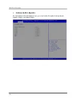
Decode I/O Size 0~5 

This field is used for the configuration IO Space size. 

Available Options:  1 Byte, 2 Byte, 4 Byte, 8 Byte, 16 Byte, 32 Byte, 64 Byte and 128Byte., 

Default setting: (128 Byte), (64 Byte), (32 Byte), (128 Byte), (64 Byte), (32 Byte) 

Summary of Contents for FB2701

Page 1: ...i FabiaTech Corporation IPC Solution Website http www fabiatech com Email support fabiatech com ISA CPU Card Low Power Series FB2701 User s Manual JULY 2019 Version 1 1 Part Number FB2701...

Page 2: ...nishing performance or use of this document Trademarks Trademarks brand names and products names mentioned in this publication are used for identification purpose only and are the properties of their...

Page 3: ...al Ports 0 1 2 3 Connectors 10 CN17 CN16 Keyboard Mouse Connector 11 CN10 RJ45 LAN Connector 11 J4 CPU or System Fan Connector 12 JP2 Clear CMOS Data 12 CN7 CN6 PCIe Mini Card or m SATA Module SIM Car...

Page 4: ...troller MAC 43 ITE8888 Setting 44 ITE8888 ISA Decode Memory 46 Chipset 47 North Bridge 48 North Bridge LVDS Config Select 50 South Bridge 51 Boot 54 CSM Parameters 56 Security 58 Save Exit 60 Chapter...

Page 5: ...isabled 68 Chapter 6 Technical Reference 69 Technical Reference 69 Physical and Environmental 69 Real Time Clock and Non Volatile RAM 69 CMOS RAM Map 71 I O Port Address Map 72 Interrupt Request Lines...

Page 6: ...vi...

Page 7: ...e to support 1GHz CPU this unit supports 10 100 1000 Base TX interface network port audio 2 SATA CFAST socket PCIe mini card socket for Wireless GPRS or m SATA 1 DIMM socket supports up to 4GB DDR3L R...

Page 8: ...ee RS232 One RS232 RS422 RS485 USB 2 0 Port Four SATA Port CFAST Socket Storage m SATA PCIe Mini Card Socket Audio Line Out And MIC In RJ45 LAN port 100 1000Mbps Realtek RTL8111F PCIe Mini Card Socket...

Page 9: ...FabiaTech Corporation 3 Layout J1 J2 CN1 CN2 CN3 CN4 CN5 CN13 CN17 CN10 CN8 JP1 J3 U20 U22 CN11 CN12 CN14 CN15 J4 BUS1 BT1 CN6 CN7 D1 D2 CN9 JP2 CN16 CN18 DIMM1...

Page 10: ...VDS LCD Connector 4 USB ports 2 0 and providing AC97 audio function PS 2 compatible keyboard and mouse interface 3 RS 232 and 1 RS 232 RS422 RS485 port Bus 16 Bit ISA PC104 PCIe 1 LED Indicator Provid...

Page 11: ...ded that you keep the diskette or CD that contains drivers and document files document copies and unused cables in the cartoon for future use The following lists the accessories that may be included i...

Page 12: ...FabiaTech Corporation 6...

Page 13: ...the CPU card from its anti static bag wear an anti static strap to prevent the generation of Electricity Static Discharge ESD The ESD may be generated by man s physical touch It may do damage to the...

Page 14: ...11 CN12 LVDS LCD Connector DF13 30 Pin Power Connector for LVDS LCD Backlight JST 5 Pin CN13 VGA Connector DB 15 CN14 Mini ATX power connector ATX 2 5 Pin CN15 ATX Power Signal JST 4 Pin 2 5mm CN16 PS...

Page 15: ...CN18 CFAST Socket The CFAST Compact Flash socket CN18 on the solder side is support CFAST Compact Flash CN18 DIMM1 CN1 CN2 Serial ATA hard Disk Connector J1 J2 CN1 CN2 CN3 CN4 CN5 CN13 CN17 CN10 CN8...

Page 16: ...CN16 CN8 CN5 CN4 CN3 Serial Ports 0 1 2 3 Connectors The Serial port 0 CN8 DB9 is designed for multiple proposes It could be RS 232 RS 422 or RS 485 by BIOS CMOS setting Use the included serial cable...

Page 17: ...s for LAN The down side LED orange indicates data is being accessed and the up side LED green indicates on line status On indicates on line and off indicates off line J1 J2 CN1 CN2 CN3 CN4 CN5 CN13 C...

Page 18: ...information like system date time boot up device password IRQ which are set up with the BIOS To clear the CMOS set JP2 to 2 3 closed and wait 3 5 sec then return to open before powers is off The defau...

Page 19: ...ll the SIM card for GPRS J1 J2 CN1 CN2 CN3 CN4 CN5 CN13 CN17 CN10 CN8 JP1 J3 U20 U22 CN11 CN12 CN14 CN15 J4 BUS1 BT1 CN6 CN7 D1 D2 CN9 JP2 CN16 Installing AK1006 kit Optional For Half Size Mini PCIe m...

Page 20: ...A30 SA1 B14 IOR B30 OSC A15 SA16 A31 SA0 B15 B31 Ground A16 SA15 A32 Ground B16 B32 Ground PC 104 C D Pin Pin Signal Pin Signal Pin Signal Pin Signal C1 GND C11 MEMW D1 Ground D11 C2 SBHE C12 SD8 D2 M...

Page 21: ...B1 12V A2 12V B2 12V A3 12V B3 12V A4 Ground B4 Ground A5 N C B5 SMBCLK A6 N C B6 SMBDATA A7 N C B7 Ground A8 N C B8 3 3V A9 3 3V B9 N C A10 3 3V B10 3 3 VSB A11 PWRGD B11 WAKE A12 Ground B12 N C A13...

Page 22: ...e input and 2 way Lineout respectively You can connect J1 Audio CN2 USB cable from FB2701 CN9 and J1 or J2 The following figure shows these Audio connectors on FB4706x board CN4 CN6 CN5 CN1 CN3 CN2 J1...

Page 23: ...gnals to a push button switch as soft power switch J1 J2 CN1 CN2 CN3 CN4 CN5 CN13 CN17 CN10 CN8 JP1 J3 U20 U22 CN11 CN12 CN14 CN15 J4 BUS1 BT1 CN6 CN7 D1 D2 CN9 JP2 CN16 Pin Signal Pin Signal 1 PS_ON...

Page 24: ...onnection to the front panel which contains the Reset button and the Power button LAN and Power LED indicator signals pin defined as shown below Pin Signal Pin Signal 1 PW Button 2 PW Button 3 RS Butt...

Page 25: ...nitor LVDS LCD Module Display LVDS LCD FLAT PANEL DISPLAY Using the BIOS setting for different types of LVDS LCD module then set your system properly and configures BIOS setting for the right type of...

Page 26: ...ial environment 254MB simulated VRAM allows a maximum VGA resolution of 1920X1080 with 32 bit at 60Hz J1 J2 CN1 CN2 CN3 CN4 CN5 CN13 CN17 CN10 CN8 JP1 J3 U20 U22 CN11 CN12 CN14 CN15 J4 BUS1 BT1 CN6 CN...

Page 27: ...Pin Signal 1 12V 2 Ground 3 ENVDD 4 N C 5 ENABLK Pin Signal Pin Signal 1 Ground 2 LVDS_FP0 3 LVDS_FP0 4 Ground 5 LVDS_FP1 6 LVDS_FP1 7 Ground 8 LVDS_FP2 9 LVDS_FP2 10 Ground 11 LVDS_CK 12 LVDS_CK 13...

Page 28: ...FabiaTech Corporation 22...

Page 29: ...irmware that interacts directly with the hardware components and facilitates interaction between the system hardware and the operating system The BIOS default values ensure that the system will functi...

Page 30: ...ns 1 Main 2 Advanced ACPI Settings CPU Configuration IDE Configuration USB Configuration SMART Settings IT8786 Super IO Configuration IT8786 HW Monitor WAKE Configuration IT8888 Configuration 3 Chipse...

Page 31: ...item The Left and Right keys allow you to select screen Enter The Enter key allows the user to select an option to edit its value or access a sub menu The Plus and Minus keys allow you to change the f...

Page 32: ...Date Time Setup Highlight the Date field and then press the keys or enter new values to set the current date Follow the month day and year format Highlight the Time field and then press the keys or e...

Page 33: ...the items in the left frame of the screen such as USB Configuration to go to the sub menu for that item You can display an Advanced BIOS Setup option by highlighting it using the Arrow keys All Advanc...

Page 34: ...ACPI Auto Configuration This item allows users to enable or disable BIOS ACPI Auto Configuration Available Options Disabled Enabled Default setting Disabled Enable Hibernation This item allows users t...

Page 35: ...Options Suspend Disabled and S1 Only CPU Stop Clock Default setting Suspend Disabled Lock Legacy Resources This item allows users to enable or disable Lock of Legacy Resources Available Options Disab...

Page 36: ...nd down Arrow keys to select an item Use the Plus and Minus keys to change the value of the selected option PSS Support This field allows users to enable or disable the generation of ACPI_PPC _PSS and...

Page 37: ...Available Options Disabled and Enabled Default setting Enabled SVM Mode When SVM Secure Virtual Machine enabled a CPU Virtualization can utilize the additional hardware capabilities Available Options...

Page 38: ...FabiaTech Corporation 32 IDE Configuration You can use this screen to select options for the SB SATA Configuration...

Page 39: ...Available Options Disabled and Enabled Default setting Enabled OnChip SATA Type Select a configuration for SATA controller Install Windows XP in AHCI mode need to use the F6 Method pre installed AHCI...

Page 40: ...operating system is fully booted with all USB drivers loaded When this option is enabled any attached USB mouse or USB keyboard can control the system even when there is no USB drivers loaded on the s...

Page 41: ...s Available Options 1 sec 5 sec 10 sec and 20 sec Default setting 20 sec Device reset time out USB mass storage device start unit command time out Available Options 10 sec 20 sec 30 sec and 40 sec Def...

Page 42: ...Options 1 5 10 20 30 and 40 Sec Default setting 5 Sec Generic Storage Device 1 01 Mass storage device emulation type AUTO enumerates devices according to their media format Optical drives are emulated...

Page 43: ...FabiaTech Corporation 37 SMART Settings SMART Self TEST Run SMART Self TEST on all HDD during POST Available Options Disabled and Enabled Default setting Disabled...

Page 44: ...FabiaTech Corporation 38 IT8786 Super IO Configuration This section describes the function of Super I O settings Serial Port 0 Configuration These fields select the I O port address for Serial port 0...

Page 45: ...isabled Default setting Enabled Device Settings Serial Port0 IO 3F8 IRQ IRQ4 Transfer Mode Setting This item allows users can select RS 232 RS 422 and RS 485 of select COM1 Available Options RS 232 RS...

Page 46: ...m allows users to select the enable or disable Serial port of select COM2 COM3 COM4 Available Options Enabled and Disabled Default setting Enabled Device Settings Serial Port1 IO 2F8 IRQ IRQ3 Serial P...

Page 47: ...FabiaTech Corporation 41 Hardware Health Configuration On the Hardware Monitor Setup screen you can monitor the system temperature1 System voltage and VBAT voltage...

Page 48: ...is field specifies the PXE boot ROM of the onboard LAN chip Available Options Disabled and Enabled Default setting Disabled Wake ON Lan This item is can select Enabled to integrated LAN to wake up the...

Page 49: ...FabiaTech Corporation 43 Realtek PCIe GBE Family Controller MAC On the LAN Information screen you can see the LAN Chipset information when setting the Launch PXE OpROM Policy to UEFI Only of CSM Boot...

Page 50: ...ctive or positive decode IO Space Available Options Subtractive Decode Positively Decode Default setting Positively Decode Memory Hole 15MB 16MB This field specifies the location of an area of memory...

Page 51: ...used for the decoding speed for IO Space Available Options Subtractive Speed Medium Speed Slow Speed and Fast Speed Default setting Subtractive Speed Decode I O Addr 0 5 15 0 These fields is used for...

Page 52: ...ecode Memory Speed 0 3 This field is used for the decoding speed for memory Space Available Options Subtractive Speed Medium Speed Slow Speed and Fast Speed Default setting Medium Speed Decode Memory...

Page 53: ...FabiaTech Corporation 47 Chipset This section describes the configuration of the board s chipset features North Bridge North Bridge LVDS Config Select South Bridge...

Page 54: ...tion 48 North Bridge You can use this screen to select options for the North Bridge Configuration Use the up and down Arrow keys to select an item Use the Plus and Minus keys to change the value of th...

Page 55: ...r GPRS Available Options Disabled and Enabled Default setting Enabled Port 5 Control Onboard LAN The onboard LAN corresponding PCI Express port 4 the item allows users to enable or disable on board PC...

Page 56: ...e of the selected option DP0 Output Mode This field specifies which LVDS display will be used when the system is boot You can select LVDS or disable booting on the LVDS Display Available Options Disab...

Page 57: ...the option controls how the PC will behave once power is restored following a power outage or other unexpected or ungraceful shutdown The Last State option returns the PC to the state in effect at th...

Page 58: ...OST Control each of the USB ports 0 1 Enable Enable USB 0 1 port Disable Use USB port 0 1 setting Available Options Disabled and Enabled Default setting Enabled USB Port 0 1 2 3 The USB Control each o...

Page 59: ...FabiaTech Corporation 53 Azalia HD Audio Audio Controller This item allows users to enable or disable Azalia Controller Available Options Disabled and Enabled Default setting Disabled...

Page 60: ...by highlighting it using the Arrow keys All Boot Setup options are described in this section Setup Prompt Timeout This item allows users to select the number of seconds to wait for setup activation k...

Page 61: ...ow disabling GA20 this option is useful when any RT code is executed above 1MB Available Options UPON REQUEST and ALWAYS Default setting UPON REQUEST Option ROM Message Set display mode for Option ROM...

Page 62: ...will show all hard disk drives attached CSM Parameters The CSM Compatibility Support Module is Option ROM Execution boot options filter etc Launch CSM This item allows users to enable or disable CSM...

Page 63: ...rage OpROM Available Options Do not Launch Legacy only UEFI only Leach First and UEFI First Default setting Legacy only Launch Video OpROM Policy This option Controls the execution of UEFI and Legacy...

Page 64: ...u select password support you are prompted for a three to twenty character password Type the password on the keyboard The password does not appear on the screen when typed Make sure you write it down...

Page 65: ...FabiaTech Corporation 59 Clear Old Password Select Administrator user password item press Enter and type current password at the next dialog press Enter to Clear Old Password...

Page 66: ...fications to the system configuration Save Changes and Reset When you have completed the system configuration changes select this option to save the changes and reboot the system so the new system con...

Page 67: ...ompleted the system configuration changes select this option to undo the previous changes Restore Defaults Restore Load Default values for all the setup options Save as User Defaults Save the changes...

Page 68: ...FabiaTech Corporation 62...

Page 69: ...on Step 3 A Catalyst Installation Folder window will open allowing the user to select the folder to which the installation files will be saved Click Install NOTE AMD recommends using the default locat...

Page 70: ...7 X86 X64 Driver Step 1 To install the AUDIO driver insert the CD ROM into the CD ROM device and enter DRIVER AUDIO ALC888_R270 Windows Step 2 Execute Setup exe file Step 3 The screen shows the SETUP...

Page 71: ...re click on Device Manager Step 4 Click on Other ISA to PCI bridge Update Driver Select Specify a location Browse Select ite inf file from CD ROM Step 5 Select ITE 8888 PCI to ISA bridge Step 6 Click...

Page 72: ...trigger the I O every time before the timer times out If your program fails to trigger or disable this timer before it times out e g because of a system hang up it will generate a reset signal to rese...

Page 73: ...to non zero value to watchdog counter and start to count down again If your program fails to trigger the watchdog timer before time out it will generate a reset pulse to reset the system The factor o...

Page 74: ...portb 0x2f 0x00 outportb 0x2e 0x73 Set Timer Value counter0 0001 00FF LSB outportb 0x2f 0x28 Set timeout interval as 28seconds and start counting Exit the extended function mode outportb 0x2e 0x02 Set...

Page 75: ...re Operating 0 C 60 C 32 140 Relative humidity 0 to 90 non condensing Real Time Clock and Non Volatile RAM The FB2701 contains a real time clock compartment that maintains the date and time in additio...

Page 76: ...us byte 10 Diskette drive type byte drive A and B 11 Fixed disk type byte drive C 12 Fixed disk type byte drive D 13 Reserved 14 Equipment byte 15 Low base memory byte 16 High base memory byte 17 Low...

Page 77: ...abled 1 Enabled 15h Base Memory in 1KB increments Low Byte 16h Base Memory in 1KB increments High Byte 17h IBM compatible memory in 1KB increments Low Byte 18h IBM compatible memory in 1KB increments...

Page 78: ...h 09Fh DMA Page Register 0A0h 0BFh Interrupt Controller 2 0C0h 0DFh DMA Controller 2 0F0h Clear Math Coprocessor Busy Signal 0F1h Reset Math Coprocessor 170h 17Fh ATA Channel 1 1F0h 1FFh ATA Channel 0...

Page 79: ...service required The following table shows the IRQ used by the devices on the Industrial CPU Card Level Function IRQ0 System Timer Output IRQ1 Keyboard IRQ2 Interrupt Cascade IRQ3 Serial Port 2 IRQ4...

Page 80: ...control capability and a processor interrupt system that may be software tailored to the computing time required to handle the communications link The following table is a summary of each ACE accessib...

Page 81: ...0 0 if Interrupt Pending Bit 1 Interrupt ID Bit 0 Bit 2 Interrupt ID Bit 1 Bit 3 Must be 0 Bit 4 Must be 0 Bit 5 Must be 0 Bit 6 Must be 0 Bit 7 Must be 0 Line Control Register LCR Bit 0 Word Length...

Page 82: ...t be 0 Line Status Register LSR Bit 0 Data Ready DR Bit 1 Overrun Error OR Bit 2 Parity Error PE Bit 3 Framing Error FE Bit 4 Break Interrupt BI Bit 5 Transmitter Holding Register Empty THRE Bit 6 Tra...

Page 83: ...LS MS LS MS Bit 0 Bit 0 Bit 8 Bit 1 Bit 1 Bit 9 Bit 2 Bit 2 Bit 10 Bit 3 Bit 3 Bit 11 Bit 4 Bit 4 Bit 12 Bit 5 Bit 5 Bit 13 Bit 6 Bit 6 Bit 14 Bit 7 Bit 7 Bit 15 Desired Baud Rate Divisor Used to Gene...

Page 84: ...e and ROM RAM memory space is D000 0 D3FF 0 16K the following steps are for you to set up the I O or memory resources manually 1 Booting the FB2701 CPU card and go into the BIOS CMOS SETTUP Advanced I...

Page 85: ...t the Decode Memory Addr 0 23 8 fill the D00 Hex D000 0 Memory Segment then set Decode Memory Size in the option of 64 KB D000 DFFF Memory segment 4 Save above BIOS CMOS SETUP F10 and restart the syst...

Page 86: ...FabiaTech Corporation 80 Appendix Dimension...

Reviews: