EN
8
8
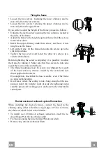
Fixing the frame
• Loosen the two screws fastening the lower chimney and re-
move this from the lower frame.
• Loosen the two screws fastening the upper chimney and re-
move this from the upper frame.
If you wish to adjust the height of the frame, proceed as follows:
• Unfasten the metric screws joining the two columns, located at
the sides of the frame.
• Adjust the frame to the height required, then refit all the screws
removed as above.
• Insert the upper chimney stack from above, and leave it run-
ning free on the frame.
• Lift up the frame, fit the frame slots onto the screws up to the
slot end positions.
• Tighten the two screws and fasten the other two screws pro-
vided with the hood.
Before tightening the screws completely it is possible to adjust
the frame by turning it. Make sure that the screws do not come
out of their seats in the slotted holes.
• The frame mountings must be secure to withstand the weight
of the hood and any stresses caused by the occasional side
thrust applied to the device.
On completion, check that the base is stable, even if the frame
is subjected to bending.
• In all cases where the ceiling is not strong enough at the sus-
pension point, the installer must provide strengthening using
suitable plates and backing pieces anchored to the structurally
sound parts.
2
2
1
1
Ducted version air exhaust system Connection
When installing the ducted version, connect the hood to the
chimney using either a flexible or rigid pipe ø 150 or 120 mm,
the choice of which is left to the installer.
• To install a ø 120 mm air exhaust connection, insert the re-
ducer flange 9 on the hood body outlet.
• Fix the pipe using the pipe clamps 25 (not provided).
• Remove any activated charcoal filters.
9
ø 150
ø 120
25
25
Summary of Contents for TRATTO ISOLA SP EG8 X/V A90
Page 1: ...Instructions Manual Manuel d Instructions Bedienungsanleitung Manual de instrucciones...
Page 3: ...3 3 64 65 68 73 74 SA...
Page 44: ...GR 4 4 44 650 mm I 120 mm 650 mm min...
Page 45: ...GR 4 5 45 650 290 898 70 90 132 433 150 350 740 740 940 572 Min 500mm Min 650mm...
Page 47: ...GR 4 7 47 21 20 mm 10 mm 11 7 mm 10 mm 4 5 mm 20 mm 12h 12g 22 23...
Page 48: ...GR 4 8 48 2 2 1 1 150 120 mm o 120 mm 9 25 9 150 120 25 25...
Page 50: ...GR 5 0 50 3 mm 1 2 27 12e 2 9 x 9 5 2 26 3 4 5 6 24 2 12e 2 9 x 9 5 7 1 2 3 4 5 6 7...
Page 51: ...GR 5 1 51 0 1 LED L 0 1 T1 0 1 1 T2 T3 T4 2 10 S1 Led 100 200 T4 T3 T2 T1 L S1 2 3 4 I F...
Page 52: ...GR 5 2 52 1 5 V LR03 AAA T3 3 led led S1 2...
Page 53: ...GR 5 3 53 led S1 4 1 led 3 T1 led T1 T4 2 Led 1 Led T3 3 led 20 W...
Page 54: ...RU 5 4 54 650 I 120 650 mm min...
Page 55: ...RU 5 5 55 650 290 898 70 90 132 433 150 350 740 740 940 572 Min 500mm Min 650mm...
Page 57: ...RU 5 7 57 21 20 10 11 7 10 4 5 20 12h 12g 22 23...
Page 58: ...RU 5 8 58 2 2 1 1 150 120 120 9 25 9 150 120 25 25...
Page 60: ...RU 6 0 60 3 1 2 27 12e 2 9 x 9 5 2 26 3 4 5 6 24 2 12e 2 9 x 9 5 7 1 2 3 4 5 6 7...
Page 61: ...RU 6 1 61 T1 L T1 1 T2 T3 T4 2 10 S1 100 200 T4 T3 T2 T1 L S1 2 3 4 I F...
Page 62: ...RU 6 2 62 1 5 LR03 AAA 3 3 1 4 S1 2...
Page 63: ...RU 6 3 63 S1 4 T1 3 T1 1 4 2 1 T3 4 20...
Page 64: ...SA 6 4 64 65 I 120 650 mm min...
Page 65: ...SA 6 5 65 650 290 898 70 90 132 433 150 350 740 740 940 572 Min 500mm Min 650mm...
Page 67: ...SA 6 7 67 21 20 10 11 7 10 4 5 20 12 H 4 4 12 G 22 23...
Page 68: ...SA 6 8 68 2 2 1 1 120 150 120 9 25 9 150 120 25 25...
Page 70: ...SA 7 0 70 1 2 27 12e 2 9 9 5 26 3 4 5 6 24 12e 2 9 905 7 1 2 3 4 5 6 7...
Page 72: ...SA 7 2 72 1 5 LR AAA T3 3 S1...
Page 73: ...SA 7 3 73 S1 4 T1 T1 T4 T3 3 20...
Page 74: ......
Page 75: ......
Page 76: ...436002315_ver4...

