18
Version 07/11 - Page 12
INSTALLATION DE LA HOTTE
1.
Retirer l’appareil de la boîte et le déposer sur une surface
plate pour l’assemblage. Couvrir la surface pour éviter tout
dommage. Retirer toutes les pièces incluant les le registre à
clapet, la grille en plastique, et nécessaire de documentation
avant de jeter la boîte. Retirer les filtres pour la graisse de
l’appareil et mettre de côté.
2.
Placer le registre rond dans l'ouverture d'échappement
de la hotte et appuyer fortement sur le registre.
3.
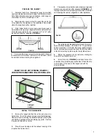
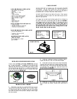
Installer la hotte sur l’armoire à l’aide de deux fixations
à ressort, une de chaque côté de la hotte (
FIGURE 5)
. Placer
la hotte dans l’ouverture pratiquée dans l’armoire. Attention
de ne pas endommager l’armoire, la hotte ou d’autres ap-
pareils.
4.
Les fixations a ressort sont fournies a la usine afin de
contenir une epaisseur compris entre 1 3/16" et 2 1/4". Si
le fond de votre armoire est profond moin de 1 3/16" est
possible d' enlever les fixations a ressort et les positionnes
en bas enlavant le 4 vis.
5.
Utiliser un tournevis Phillips et serrer la vis de reglement
tandis que les fixations s'attachent fortement à la surface.
FIGURE 4
FIGURE 5
DÉCOUPER L'OUVERTURE Où LA HOTTE SERA INSTALLÉE (FIGURE 4).
7.
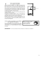
Retirer le couvercle du compartiment de filage. Passer
le câble d’alimentation dans la pastille enfonçable. Attacher
le fil blanc du câble d’alimentation sur le fil blanc de la hotte
avec une cosse. Attacher le fil noir du câble d’alimentation
au fil noir de la hotte avec une cosse. Brancher le fil de
mise à la terre vert (jaune et vert) sous la vis de mise à
la terre verte. Utiliser les quatre trous fournis et fixer le
compartiment de filage au mur ou à l'armoire, déterminé par
l'emplacement du câble d’alimentation (vis non fournies).
Replacer le couvercle.
8.
Replacer les filtres pour la graisse.
9.
Brancher le conduit sur le registre et sceller toutes
les connexions avec du ruban à conduit.
10.
Mettre l’alimentation en circuit. Mettre en circuit le
ventilateur et la lumière. Si la hotte ne fonctionne pas, vérifier
si le disjoncteur n’est pas fermé ou si le fusible n’est pas
grillé. Si l’appareil ne fonctionne toujours pas, débrancher
l’alimentation et vérifier si les connexions ont été effectuées
correctement.
6.
Une bande
(FIGURE 6)
est incorporee dans l' embal-
lage afin de couvrir la partie inferieure a vis de l'armoire. La
bande est fixee sur la partie inferieure en bas de la hotte par
deux vis .
FIGURE 6
CUT-OUT
EN
88
INSTALLATION
Drilling the Support surface and Fitting the Hood
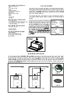
SCREW FITTING
• The hood support surface must be 8” 11/16 above the bottom
surface of the wall units.
• Drill the support with a ø 3/16”drill bit, using the drilling tem-
plate provided.
• Cut a hole ø 6”in size on the support surface, using the drilling
template provided.
• Fix using the 4 screws
12a
provided.
����
����
���
SNAP-ON FITTING
• The hood can be installed either directly on the bottom surface
of the wall units using snap-on side supports.
• Cut a fitted opening in the bottom surface of the wall unit, as
shown.
• Insert the hood until the side supports snap into place.
• Lock in position by tightening the screws
Vf
from underneath
the hood.
�����
��������
��������������������
��
CLOSING ELEMENT
• The space between the edge of the hood and the rear wall can
be closed by applying the element
20
provided, using the
screws supplied for this purpose.
��
19
3/4
"
10
3/8
"
Summary of Contents for Cristal 24 SS
Page 35: ...35...

