background image

19

OPERATING THE CONTROLS

FOR BEST RESULTS

Start the Range Hood several minutes before cooking to develop proper airflow. Allow the 

Range Hood to operate for several minutes after cooking is complete to clear all smoke and 
odors from the kitchen.

T1

T2

T3

T4

L

Button Function

T1

T2

T3

T4

L

Fan Off Button:Turn the blower Off. 
The fan can be operated by pressing any of the fan setting buttons.
Hold down this button for 2 seconds to activate delayed off function which will 
keep the fan On for 15 minutes and automatically shut Off.

T1

T2

T3

T4

L

Fan Settings Buttons: Low Speed.

T1

T2

T3

T4

L

Fan Settings Buttons: Medium Speed.

T1

T2

T3

T4

L

Fan Settings Buttons: High Speed.
Hold down the button for 2 seconds to activate the INTENSIVE SPEED, which is timed 
to run for 10 minutes. At the end of this time it will automatically return to the speed set 
before.Suitable to deal with maximum levels of cooking fumes.

T1

T2

T3

T4

L

Light Button:  On / Off for the LED lights. Press the LIGHT button to turn the light 
on, again to turn off. 

NOTE: If your product has had a CFM adjustment, refer to the CFM adjustment manual for the 
information. Some motor speeds or functions may be reduced.

Summary of Contents for CLASSICA PLUS CLPL30SSV2

Page 1: ...CLPL30SSV2 CLPL36SSV2 Installation Instructions Use and Care Information Instructions d installation Utilisez et d entretien Instrucciones de instalaci n Informaci n de uso y cuidado CLASSICA PLUS...

Page 2: ...nstallation height requirements 7 Parts 8 Tools needed 9 Ducted venting method options 10 Mounting Range Hood on wall 11 Non Ducted Recirculation Option 17 Connecting electricity 18 Operating the cont...

Page 3: ...ment is being called 4 You can fight the fire with your back to an exit Based on Kitchen Firesafety Tips published by NFPA WARNING TOREDUCETHERISKOFFIREORELECTRICSHOCK donotusethisfanwith any solid st...

Page 4: ...nd either through the wall or the roof The length of the ductwork and the number of elbows should be kept to a minimum to provide efficient performance The size of the ductwork should be uniform Do no...

Page 5: ...ear the field wiring compartment Electrical ground is required on this Range Hood If cold water pipe is interrupted by plastic nonmetallic gaskets or other materials DO NOT use for grounding DO NOT gr...

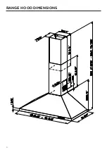
Page 6: ...6 RANGE HOOD DIMENSIONS...

Page 7: ...7 MIN 24 OVER ELECTRIC MIN 30 OVER GAS INSTALLATION HEIGHT REQUIREMENTS Min 30 Min 24...

Page 8: ...A Hood body Includes Controls Light Filters Blower 1 B Damper 1 C Lower Chimney 1 D Upper Chimney 1 E Chimney wall brackets 2 REF PART F Pozi Screws 3 16 x 1 3 4 8 G Pozi Screws 1 8 x 7 16 4 PARTS IN...

Page 9: ...rchased separately TOOLS NEEDED TOOL Tape Measure Pencil Electric Drill with 5 16 Drill Bit Phillips Screwdriver Work gloves ACCESSORIES AVAILABLE ACCESSORY SKU DUCTLESS KIT CLAS DIVERTER CHARCOAL DUC...

Page 10: ...10 DUCTED VENTING METHOD OPTIONS DUCTED WITH 7 ROUND OUTLET Vertical Horizontal NON DUCTED RECIRCULATION OPTION Requires purchase of Activated Charcoal Accessory Horizontal Vertical 6...

Page 11: ...the center of the area in which the hood will be installed Draw a horizontal line I from where the bottom edge of the hood will be located to a minimum of 24 above an electric cooking surface and 30 a...

Page 12: ...e bracket Place the second bracket E on the wall as shown below the first bracket at the height of the upper chimney section D supplied and aligning the centers notch with the vertical line Mark the w...

Page 13: ...rews supplied F into the wall as shown onto holes 1 and 2 Hang the hood on the wall by pushing the screws through the 2 designated key holes on the back of the hood Tighten the screws 4 Pozi Screwdriv...

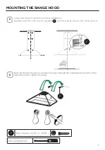
Page 14: ...rk the holes for the two security holes drill a 5 16 x 2 where marked Insert 2 wall plugs into the holes and tightly screw 2 screws F 5 MOUNTING THE RANGE HOOD Pozi Screwdriver F Pozi Screws 3 16 x 1...

Page 15: ...or Wall Cap purchased separately Connect the 6 metal ductwork to the Roof or Wall Cap and then attach ductwork MOUNTING THE RANGE HOOD 6 Attach the 2 chimney brackets E using 4 screws F supplied 7 L 4...

Page 16: ...o the brackets E by using the 4 screws G Slightly widen the two sides of the lower chimney and hook them between the upper section and the wall making sure that they are properly housed 9 10 N 4x D C...

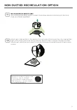
Page 17: ...to the black grid on each side of the blower Press the charcoal filter tightly to the black grid on the blower side and rotate the filter clockwise towards the front of the hood until it locks into pl...

Page 18: ...t in a risk of electric shock Consult a qualified electrician if the grounding instructions are not completely un derstood or if doubt exists as to whether the appliance is properly grounded Do not us...

Page 19: ...ep the fan On for 15 minutes and automatically shut Off T1 T2 T3 T4 L Fan Settings Buttons Low Speed T2 T3 T4 L Fan Settings Buttons Medium Speed T3 T4 L Fan Settings Buttons High Speed Hold down the...

Page 20: ...as shown Insert the hood until the side supports snap into place Fasten using the 10 screws 12a provided Lock in position by tightening the screws Vf from underneath the hood Open the suction panel b...

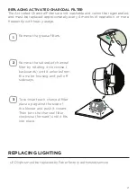
Page 21: ...by rotating it clockwise backwards until it unlocks from the motor housing and pull off sideways To re insert each charcoal filter place up against the side of the blower and push it inward Then turn...

Page 22: ...22 WIRING DIAGRAM 120V 60Hz...

Page 23: ...ay repair or replace the product or components necessary to restore the product to good working condition Franke Home Solutions Warranty for Franke and Faber Branded Product Effective March 1 2022 In...

Page 24: ...ents do not include liability for project delays Product replacements are not guaranteed to be exact replacements If the original product is not available at the time of the warranty claim at Franke s...

Page 25: ...ur d installation 29 Pi ces 30 Outils n cessaires 31 Options de la m thode d vacuation par conduits 32 Fixation murale de la hotte 33 Option de recirculation sans conduit 39 Branchement lectrique 40 U...

Page 26: ...re le feu en tournant le dos une sortie Bas sur les Conseils de s curit pour la cuisine publi par la NFPA AVERTISSEMENT POUR R DUIRE LE RISQUE D INCENDIE OU DE CHOC LECTRIQUE n utilisez pas ce ventila...

Page 27: ...ongueur des conduits et le nombre de coudes doivent tre r duits au minimum pour assurer une performance efficace La taille des conduits doit tre uniforme N installez pas deux coudes ensemble Utilisez...

Page 28: ...iment de c blage Une mise la terre lectrique est requise sur cette hotte Si le tube d eau froide est interrompu par du plastique des joints non m talliques ou d autres mat riaux NE l utilisez PAS pour...

Page 29: ...29 DIMENSIONS DE LA HOTTE...

Page 30: ...30 MIN 24 AU DESSUS DE L LECTRICIT MIN 30 SUR GAZ EXIGENCES EN MATI RE DE HAUTEUR D INSTALLATION Min 30 Min 24...

Page 31: ...s les commandes l clairage les filtres le ventilateur 1 B Clapet anti retour 1 C Chemin e inf rieure 1 D Chemin e sup rieure 1 E Supports muraux de chemin e 2 R F PI CE F Vis Pozi 3 16 x 1 3 4 8 G Vis...

Page 32: ...toit doit tre achet s par ment OUTILS N CESSAIRES OUTIL M tre ruban Crayon Perceuse lectrique avec m che de 5 16 Tournevis Phillips Gants de travail ACCESSOIRES DISPONIBLES ACCESSOIRES SKU KIT SANS C...

Page 33: ...TIONS DE LA M THODE D VACUATION PAR CONDUITS Conduit avec sortie ronde de 7 Vertical Horizontal OPTION DE RECIRCULATION SANS CONDUIT N cessite l achat de l accessoire charbon actif Horizontale Vertica...

Page 34: ...de la zone o la hotte sera install e Tracez une ligne horizontale I partir de l endroit o le bord inf rieur de la hotte sera situ jusqu un minimum de 24 au dessus d une surface de cuisson lectrique et...

Page 35: ...Placez le deuxi me support E sur le mur comme indiqu sous le premier support la hauteur de la section de chemin e sup rieure D fournie et en alignant les centres encoche avec la ligne verticale Marque...

Page 36: ...les deux vis fournies F dans le mur comme indiqu dans les trous 1 et 2 Accrochez la hotte au mur en poussant les vis travers les 2 trous indiqu s l arri re de la hotte Serrez les vis 4 Tournevis Pozi...

Page 37: ...les trous pour les deux trous de s curit percez un 5 16 x 2 l endroit indiqu Ins rez 2 chevilles dans les trous et vissez fermement 2 vis F 5 MONTAGE DE LA HOTTE D ASPIRATION Tournevis Pozi F Vis Poz...

Page 38: ...r achet s par ment Raccordez le conduit m tallique de 6 pouces au capuchon de toit ou de mur puis fixez le conduit MONTAGE DE LA HOTTE D ASPIRATION 6 Fixez les 2 supports de chemin e E l aide des 4 vi...

Page 39: ...s aux supports E l aide des 4 vis G largissez l g rement les deux c t s de la chemin e inf rieure et accrochez les entre la section sup rieure et le mur en vous assurant qu ils sont bien en place 9 10...

Page 40: ...noire de chaque c t du ventilateur Appuyez fermement le filtre charbon sur la grille noire du c t du ventilateur et tournez le filtre dans le sens horaire vers l avant de la hotte jusqu ce qu il se v...

Page 41: ...choc lectrique Consultez un lectricien qualifi si vous ne comprenez pas parfaitement les in structions de mise la terre ou si vous avez des doutes quant la mise la terre de l appareil N utilisez pas...

Page 42: ...s et l arr te automatiquement T1 T2 T3 T4 L Boutons de r glage du ventilateur Basse vitesse T2 T3 T4 L Boutons de r glage du ventilateur Vitesse moyenne T3 T4 L Boutons de r glage du ventilateur Haute...

Page 43: ...nto place Fasten using the 10 screws 12a provided Lock in position by tightening the screws Vf from underneath the hood Open the suction panel by turning the specific knob Disconnect the panel from th...

Page 44: ...jusqu ce qu il se d verrouille du bo tier du moteur et retirez le lat ral ement Pour r ins rer chaque filtre charbon placez le contre le c t du ventilateur et pous sez le vers l int rieur Tournez ensu...

Page 45: ...45 SCH MA DE C BLAGE 120 V 60 Hz...

Page 46: ...ts d taill es dans le pr sent document chacune une garantie et collectivement les garanties Les produits doivent tre correctement install s conform ment aux instructions d installation de Franke dans...

Page 47: ...Product replacements are not guaranteed to be exact replacements If the original product is not available at the time of the warranty claim at Franke s option the product replacements will be of simi...

Page 48: ...alaci n 53 Piezas 54 Herramientas necesarias 55 Opciones del m todo de ventilaci n por conductos 56 Montaje de la campana extractora en la pared 57 Opci n de recirculaci n sin conductos 63 Conexi n de...

Page 49: ...omberos 4 Puede combatir el fuego de espaldas a una salida Basado en Consejos de Seguridad contra Incendios en la Cocina publicado por la NFPA ADVERTENCIA PARAREDUCIRELRIESGODEINCENDIOODESCARGAEL CTRI...

Page 50: ...l n mero de codos deben reducirse al m nimo para conseguir un rendimiento eficaz El tama o de la red de conductos debe ser uniforme No instale dos codos juntos Utilice cinta adhesiva para sellar todas...

Page 51: ...mparti miento de cableado de campo Esta campana extractora requiere una toma de tierra el ctrica Si la tuber a de agua fr a est interrumpida por pl stico juntas no met licas u otros materiales NO la u...

Page 52: ...52 DIMENSIONES DE LA CAMPANA EXTRACTORA...

Page 53: ...53 M N 24 SOBRE EL CTRICO M N 30 SOBRE GAS REQUISITOS DE ALTURA PARA LA INSTALACI N M n 30 M n 24...

Page 54: ...na Incluye controles luz filtros soplador 1 B Amortiguador 1 C Chimenea inferior 1 D Chimenea superior 1 E Soportes de pared para chimenea 2 REF PIEZA F Tornillos Pozi 3 16 x 1 3 4 8 G Tornillos Pozi...

Page 55: ...or separado HERRAMIENTAS NECESARIAS HERRAMIENTA Cinta M trica L piz Taladro El ctrico con Broca de 5 16 Destornillador Phillips Guantes de trabajo ACCESORIOS DISPONIBLES ACCESORIO SKU KIT CLAS SIN CON...

Page 56: ...NES DEL M TODO DE VENTILACI N POR CONDUCTOS CONDUCTO CON SALIDA REDONDA DE 7 Vertical Horizontal OPCI N DE RECIRCULACI N SIN CONDUCTOS Requiere la compra del accesorio de carb n activado Horizontal Ve...

Page 57: ...na en la que se instalar la campana Trace una l nea horizontal I desde el lugar donde se ubicar el borde inferior de la campana hasta un m nimo de 24 por encima de una superficie de cocci n el ctrica...

Page 58: ...segundo soporte E en la pared como se muestra debajo del primer so porte a la altura de la secci n superior de la chimenea D suministrada y alineando los centros muesca con la l nea vertical Marque l...

Page 59: ...en la pared como se muestra en los orificios 1 y 2 Cuelgue la campana en la pared empujando los tornillos a trav s de los 2 orificios de llave designados en la parte posterior de la campana Apriete l...

Page 60: ...a los dos orificios de seguridad taladre 5 16 x 2 donde est marcado Inserte 2 tacos de pared en los orificios y atornille firmemente los 2 tornillos F 5 MONTAJE DE LA CAMPANA EXTRACTORA Destornillador...

Page 61: ...d comprada por separado Conecte el conducto met lico de 6 a la Tapa del Techo o de la Pared y luego fije el conducto MONTAJE DE LA CAMPANA EXTRACTORA 6 Fije los 2 soportes de la chimenea E usando los...

Page 62: ...los soportes E usando los 4 tornillos G Ensanche ligeramente los dos lados de la chimenea inferior y eng nchelos entre la secci n superior y la pared asegur ndose de que queden bien alojados 9 10 N 4x...

Page 63: ...ra de cada lado del soplador Presione el filtro de carb n con firmeza en la rejilla negra del lado del soplador y gire el filtro en el sentido de las agujas del reloj hacia la parte delantera de la ca...

Page 64: ...ede suponer un riesgo de descarga el ctrica Consulte a un electricista cualificado si las instrucciones de conexi n a tierra no se entienden completamente o si existen dudas sobre si el aparato est co...

Page 65: ...urante 15 minutos y se apagar autom ticamente T1 T2 T3 T4 L Botones de configuraci n del ventilador Velocidad baja T2 T3 T4 L Botones de configuraci n del ventilador Velocidad media T3 T4 L Botones de...

Page 66: ...into place Fasten using the 10 screws 12a provided Lock in position by tightening the screws Vf from underneath the hood Open the suction panel by turning the specific knob Disconnect the panel from...

Page 67: ...ee de la carcasa del motor y tire hacia el lateral Para volver a colocar cada filtro de carb n col quelo contra el lateral del ventilador y presi ne lo hacia dentro Despu s gire el filtro de carb n ha...

Page 68: ...68 DIAGRAMA DE CABLEADO 120V 60Hz...

Page 69: ...o de Franke o Faber de acuerdo con las garant as espec ficas del producto que se detallan en este documento cada una una Garant a y colectivamente las Garant as Los productos deben ser instalados corr...

Page 70: ...ot guaranteed to be exact replacements If the original product is not available at the time of the warranty claim at Franke s option the product replacements will be of similar size material and value...

Page 71: ...71...

Page 72: ...991 0687 417_01 220824 D00008874_00...

Reviews: