background image

About the 2000/4000 Series platform

Before you install the 2000/4000 Series platform, review helpful information about the controls and ports
located on both the front and the back of the platform.

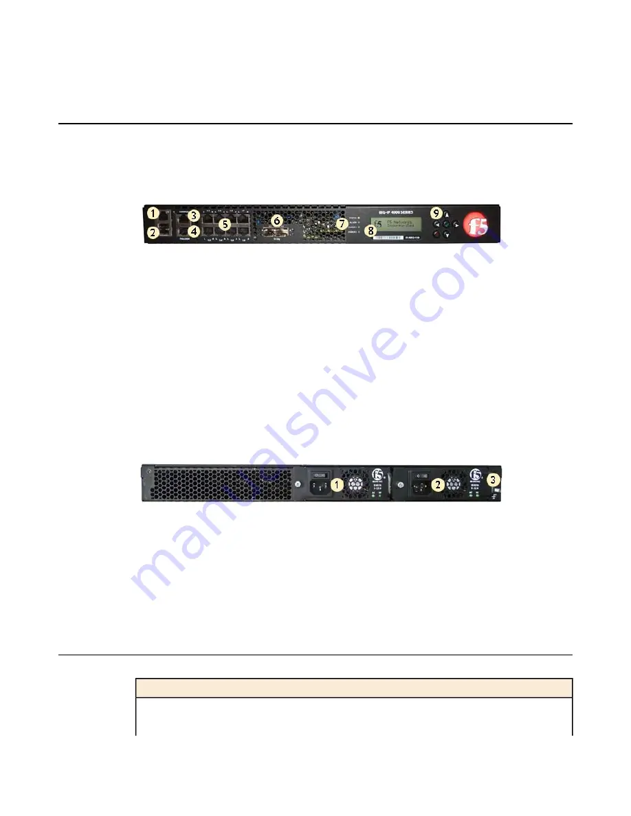
On the front of the platform, you can reset the unit using the LCD panel. You can also use the front-panel
LEDs to assess the condition of the unit. On the back of the unit, you can power off the main power.

1. Management 10/100/1000 Ethernet port

2. USB ports

3. Console serial port

4. Serial (hard-wired) failover port

5. 10/100/1000 interfaces

6. 1/10G SFP+ ports

7. Indicator LEDs

8. LCD display

9. LCD control buttons

Figure 1: Front view of the platform

The back of the platform includes one power supply by default. Optionally, you can install a second power
supply.

1. Power input panel 1 (power switch and power receptacle)

2. Power input panel 2 (power switch and power receptacle)

3. Chassis ground lug (with cover)

Figure 2: Back view of the platform

Components provided with the platform

When you unpack the platform, verify that the following components are included.

Hardware

Quantity

Power cable (black), AC power only

1

DC terminal block plug, DC power option only

1

8

About the 2000/4000 Series Platform

Summary of Contents for 2000 Series

Page 1: ...Setting Up the 2000 4000 Series Platform MAN 0400 01 ...

Page 2: ......

Page 3: ...ting kit to use 13 About the front mounting kit 13 Front mounting kit hardware 13 Installing using a front mounting kit 13 About the quick install rail kit 14 Installing the rail lock brackets 15 Connecting the cables and other hardware 16 Configuring a management IP address using the LCD panel 17 Appendix A Environmental Guidelines 19 General environmental guidelines 20 Guidelines for AC powered ...

Page 4: ...4 Table of Contents ...

Page 5: ...Browser Referencing Intelligent Compression IPv6 Gateway iApps iControl iHealth iQuery iRules iRules OnDemand iSession IT agility Your way L7 Rate Shaping LC Link Controller Local Traffic Manager LTM Message Security Module MSM Netcelera OneConnect Packet Velocity Protocol Security Module PSM Real Traffic Policy Builder ScaleN SSLAcceleration StrongBox SuperVIP SYN Check TCP Express TDR TMOS Traff...

Page 6: ...s Operation of this equipment in a residential area is likely to cause harmful interference in which case the user at his own expense will be required to take whatever measures may be required to correct the interference Any modifications to this device unless expressly approved by the manufacturer can void the user s authority to operate this equipment under part 15 of the FCC rules Canadian Regu...

Page 7: ...atform The BIG IP 2000 4000 Series platform is a powerful system that is capable of managing traffic for any size of enterprise Topics About the 2000 4000 Series platform Components provided with the platform Peripheral hardware requirements ...

Page 8: ...ed failover port 5 10 100 1000 interfaces 6 1 10G SFP ports 7 Indicator LEDs 8 LCD display 9 LCD control buttons Figure 1 Front view of the platform The back of the platform includes one power supply by default Optionally you can install a second power supply 1 Power input panel 1 power switch and power receptacle 2 Power input panel 2 power switch and power receptacle 3 Chassis ground lug with co...

Page 9: ... interface cards that are installed in the platform You can use either 10 100 1000 Ethernet or 10 Gigabit Ethernet switches Network hubs switches or connectors to connect to the platform network interfaces You can use any USB certified CD DVD mass storage device or a USB flash drive for installing upgrades and for system recovery External USB CD DVD drive or USB flash drive Note External CD DVD dr...

Page 10: ...10 About the 2000 4000 Series Platform ...

Page 11: ...you can install the unit Topics About general recommendations for rack mounting Unpacking the platform Determining which rack mounting kit to use About the front mounting kit About the quick install rail kit Installing the rail lock brackets Connecting the cables and other hardware Configuring a management IP address using the LCD panel ...

Page 12: ...y recommends that at least two people perform the installation Important This product is sensitive to electrostatic discharge ESD F5 Networks recommends that you use proper ESD grounding procedures and equipment when you install or maintain the unit Unpacking the platform The platform ships in a custom designed package that protects the product during shipment Due to the weight of the platform the...

Page 13: ...orm differ depending on the type of rack mount you decide to use or which type of cabinet unit you are installing into single two post cabinet or four post cabinet About the front mounting kit You can use the front mounting kit if you are installing into a two post rack Front mounting kit hardware The front mounting kit includes these hardware parts Hardware Quantity Front mounting brackets 2 Inst...

Page 14: ... if you want to be able to slide the unit in or out of the rack for maintenance activities The kit includes two rails left and right and eight 8 32 thumb screws The rails snap into place in the rack and no tools are required to install a platform using this kit The rails are optimized for installation into square hole cabinets but they can be installed in other cabinet styles such as round hole ca...

Page 15: ...unit using the rail lock screws that are included in the kit 2 Secure the rail lock brackets to the rack on each side of the unit using either the two 8 32 pan head Philips screws that are included with the kit or screws provided by the rack manufacturer Use 18 to 20 inch pounds 2 0 to 2 3 Newton meters of torque on these screws 15 Setting Up the 2000 4000 Series Platform ...

Page 16: ...d CAT5 cable connect the RJ45F to RJ45M rolled serial adapter to the console port and then connect a CAT5 cable to the adapter Figure 4 The RJ45F to RJ45M rolled serial pass through adapter 2 For a redundant system configuration with hard wired failover capacity connect the serial failover cable to the failover port on each unit 3 For AC powered systems connect the power cable to the power input p...

Page 17: ... 3 Press the Check button to select Management 4 Press the Check button to select Address Type and then press the Check button again to select either IPv4 or IPv6 5 Use the arrow keys to select Mgmt IP and press the Check button 6 Use the arrow keys to configure the management IP address 7 Use the arrow keys to select Prefix Length and press the Check button 8 Use the arrow keys to configure the l...

Page 18: ...18 Platform Installation ...

Page 19: ...Appendix A Environmental Guidelines Topics General environmental guidelines Guidelines for AC powered equipment Guidelines for DC powered equipment ...

Page 20: ...he air temperature in the room to exceed 104 F 40 C Do not plug the unit into a branch circuit shared by more electronic equipment than the circuit is designed to manage safely at one time Important This product is sensitive to electrostatic discharge ESD F5 Networks recommends that you use proper ESD grounding procedures and equipment when you install or maintain the unit Caution Customers should...

Page 21: ...lled in a RESTRICTED ACCESS LOCATION such as a central office or customer premises environment Note The following guidelines apply to STATIONARY PLUGGABLE EQUIPMENT TYPE A with simultaneous multiple connections to the AC MAINS SUPPLY The building installation shall provide a means for connection to protective earth and The equipment is to be connected to that means and A SERVICE PERSON shall check...

Page 22: ... branch circuit protection device to install the unit For permanently connected equipment incorporate a readily accessible disconnect in the fixed wiring Use only copper conductors Cabling for the system must be grounded on both sides Use one power feed for each individual power supply 22 Environmental Guidelines ...

Page 23: ...ning any equipment contact F5 Networks to obtain a Return Material Authorization RMA case number Important You must use shipping materials and packaging provided by F5 Networks when repackaging the platform Note Be sure that you keep a record of the tracking number and ship date These will be needed to track lost shipments Note Do not include any cables removable XFP SFP modules GBICs or other per...

Page 24: ...d other cables from the platform and then remove any optical modules 2 Remove the platform from the rack 3 Place the platform in the plastic bag if available 4 Place the foam inserts on the front and back sides of the platform 5 Place the platform into the shipping box 6 Place the accessory boxes in the foam inserts 24 Repackaging Guidelines ...

Page 25: ...7 Close and seal the shipping box 25 Setting Up the 2000 4000 Series Platform ...

Page 26: ...26 Repackaging Guidelines ...

Page 27: ...ment interface 16 management IP address configuring using LCD panel 17 N NEBS air temperature 20 P pass through adapter See RJ45F to RJ45M rolled serial adapter platform about 8 installing 11 repackaging 24 unpacking 12 ventilation 20 platform components 8 power cable 16 Q qkview utility 16 quick install rail kit 14 R rack mount front mount 13 general environmental guidelines 20 quick install rail...

Page 28: ...terminal hardware installation and 9 16 switches 9 T transporting the platform 23 two post rack 13 U unpacking platform 12 USB port supported CD DVD ROM drives 9 USB thumb drives support for 9 W warnings environmental 20 28 Index ...

Reviews:

Related manuals for 2000 Series