background image

ATR833A-II / P/N 833-II (Axxx)-(Axxx) 

Operation and Installation 


53 

Doc.-No. 01.143A.010.71e / Revision 1.00 

Notes: 


Summary of Contents for ATR833A-II-OLED

Page 1: ...k e f u n k e means fabrication utilities network know how engineering Operation and Installation Dokument Nr 01 143A 010 71e P N 833 II Axxx Axxx ATR833A II OLED VHF Communication Transceiver ...

Page 2: ...e Revision 1 00 2 Change History Revision Date Description of Change 1 00 04 04 2018 First Release Head SW 1 05 NF FW 3 00 List of Service Bulletins SB Service Bulletins are to be inserted in the manual and to be recorded in this table SB Number Rev No Date of Issue Entry Date Name ...

Page 3: ...8 2 5 3 VOX Voice Activated Intercom 18 2 5 4 INT Volume Intercom 19 2 5 5 STL Volume Sidetone Left 19 2 5 6 STR Volume Sidetone Right 20 2 5 7 EXT Volume of the external Audio Input 20 2 5 8 BRT Brightness 21 2 6 TRANSMISSION 21 2 7 RECEPTION 22 2 8 REPLAY FUNKTION 22 2 9 DUAL WATCH OPERATION 22 3 CONFIGURATION 25 3 1 SPACING CHANNEL SPACING 25 3 2 DISPLAY ENERGY SAVING MODE AUTOMATIC DISPLAY DAR...

Page 4: ...ion 38 4 6 2 Headset Connection 38 4 6 3 Audio Input 39 4 7 WIRING 39 4 7 1 Conductor Cross Section 39 4 7 2 Connector Pin Allocation 40 4 7 3 Wiring with Cable Harness BSKS833x S 42 4 8 ANTENNA 43 4 8 1 Antenna Selection 43 4 8 2 Installation Recommendation 44 4 9 MICROPHONE INTERCOM SETTINGS 44 4 10 POST INSTALLATION CHECK 45 4 11 DRAWINGS 46 4 11 1 Dimensions 46 4 11 2 Mounting Advices 47 5 APP...

Page 5: ...to the human body or ignition of combustible materials Advices whose non observance can cause damage to the device or other parts of the equipment Information 1 2 Abbreviations Abb Name Subject Definition BRT Brightness Display Brightness EXT External Audio Input Volume of external audio input INT Intercom Volume of board internal intercom MIC Microphone Sensitivity of Microphone PTT Push To Talk ...

Page 6: ...Equipment Characteristics VHF communication transceiver with 6W output power in 160mm format Frequency range 118 000 to 136 975 MHz 2 microphone inputs auto detection standard or dynamic Voice controlled intercom for up to 4 microphones can be deactivated for use with an external intercom Dual watch technology simultaneous monitoring of two frequencies Auxiliary audio input Memory for 20 user defi...

Page 7: ...n press button for appr 0 5 s Swich Off press button for appr 3 s DW DUAL WATCH Activates deactivates the mode for mutual reception of standby frequency display shows DW instead of SBY SET EINGABE 1 Navigation through the standard menu VOL SQL VOX etc adjustment of value with VOL SEL short press of SET for next value 2 Access to setup menu Press button for min 5 seconds 3 Navigation through the se...

Page 8: ... MEM List press button for 2 seconds VOL SEL VOL SEL Turn knob 1 Adjust volume or other item selected by SET VOL SQ VOX DIM etc 2 Select frequency from user memory or list of last used frequencies FREQ FREQ Turn knob Change the underlined value i e adjust standby frequency or input character when entering name 2 2 ON OFF Commissioning Turn the device on with I O Switch On I O press for appr 0 5 se...

Page 9: ...ot activated Dual watch mode allows intermittent monitoring of standby frequency activity DW Label for standby frequency when dual watch mode is activated Dual watch mode allows intermittent monitoring of standby frequency activity 118 000 Active Frequency Frequency used for trans missions and receptions 124 910 Standby frequency May be monitored in dual watch mode RX Receiving on this frequency U...

Page 10: ... the intercom DUOWATCH 2 Dual Watch Mute Reduction in volume for dual watch reception on standby frequency INT 04 Intercom Volume EXT 02 Volume of external audio signals Set to 00 if no external device is connected to prevent noise pickup BRT 07 Brightness of display CON 05 Contrast of display only for LCD MEM 00 Item from user defined frequency list 20 entries possible Substitutes Standby Frequen...

Page 11: ... width 8 33 kHz or 25 kHz is automatically determined by the value of the frequency entered and requires no additional user activity The numbering scheme that is used for distinction of the two channel widths is internationally standardized by the ICAO and consistently used in official documents like e g VFR navigation charts as well as in the voice phraseology used by ATC radio communication Chan...

Page 12: ...er active frequency When having the channel selection configured for 8 33 kHz steps see 3 1 the frequency is input in three steps SBY 118 910 SBY 118 910 SBY 118 910 In order to speed up the entering of new frequencies it is possible to configure the radio to allow entering of those frequencies only that are used with 25 kHz channel width Please refer to chapter 3 1 for information on this configu...

Page 13: ...quency In the lower row of the display the number of the memory entry selected is indicated by MEM xx with xx 1 to 20 if a name has been provided by the user for this memory entry it is displayed next to the memory entry number ACT 123 450 SBY 118 275 MEM 2 Range 01 20 Repectively ACT 123 450 SBY 118 275 MEM 2 E D N E A push on the swap button replaces the Active Frequency a press on the SET butto...

Page 14: ... twice and select one of the 10 list entries with the VOL SEL turn knob The selected memory entry substitutes the former standby frequency The number of the selected list entry is given in the display s lower row ACT 123 450 SBY 118 275 LST 2 Range 1 10 Respectively ACT 123 450 SBY 118 275 LST 2 E D N E 8 digits A Z 0 9 If there is no input for 10 seconds the device returns to the standard view Li...

Page 15: ... set as standby frequency ACT 118 275 SBY 124 350 VOL 05 2 Enter memory list With a long press on MEM the frequency can be stored to the user memory ACT 118 275 SBY 124 350 MEM saveTo 1 3 Select memory position Selection of the decided memory position with VOL SEL ACT 118 275 SBY 124 350 MEM saveTo 7 4 Overwrite the selected memory With a short press of MEM the standby frequency is stored at the s...

Page 16: ...a standby frequency ACT 118 275 SBY 123 450 MEM 7 E D T Z 7 Store the name The new entry is either stored with a long press of MEM or by a short press on the Cursor button ACT 118 275 SBY 123 450 MEM 7 E D T Z To exit the frequency list press the SET button or wait 10 seconds until time out 2 4 6 ATR Frequency Tool The ATR Frequency Tool from Version 1 3 upwards supports the ATR833A II With the to...

Page 17: ...ith LCD back to Volume The return to the default display VOL is carried out by a short press on the Dualwatch button DW or happens automatically after 10 seconds of inactivity The chosen setting can be adjusted by the VOL SEL rotary knob 2 5 1 VOL Volume The radio returns automatically to the volume setting when a value has been set with the VOL SEL turn knob Turning the VOL SEL knob adjusts the v...

Page 18: ...s an initial higher setting is typically appropriate gliders may use a lower value A lower number means higher input sensitivity This allows reception of weaker signals radio stations at higher distance but can also result in pickup of own aircraft radio interference sources engine strobe lights 2 5 3 VOX Voice Activated Intercom By shortly pressing the SET key twice with the help of the rotary kn...

Page 19: ...for multi seater aircraft A change in the intercom volume level also changes the volume of the sidetone The sidetone is an audible feedback of the own voice to the headset i e you hear yourself speak This feature supports a natural speech behavior The intercom can be activated in two ways Automatically i e whenever someone speaks into a microphone i e voice activated intercom VOX see chapter 0 Man...

Page 20: ...put By shortly pressing the SET key six times the volume of external audio signals warning tones music etc can be controlled with the rotary knob The higher the value the higher is the volume of the external audio signal A value of EXT 0 deactivates the external audio input ACT 123 450 SBY 118 275 EXT 5 Range Off 1 20 When no other device is connected to the external audio input the input should b...

Page 21: ...rts transmission on the active frequency The operation of the transmission is indicated by TX in front of the frequency used ACT TX 123 450 SBY 118 275 VOL 5 In order to avoid unintended transmissions e g when having the PTT button stuck stuck mic the transmitter automatically stops after 35 5 seconds of transmission and Te is shown for 1 second The unit returns to reception mode ACT Te 123 450 SB...

Page 22: ...the last received radio message The display will show R E P L A Y for the duration of the playback ACT 123 450 DW 118 275 VOL 5 R E P L A Y As long as a radio call is received the REPLAY function is deactivated This also means that the squelch setting must not be zero 2 9 DUAL WATCH Operation The ATR833A II comprises one receiver therefore dual watch simultaneously monitoring two frequencies is im...

Page 23: ... mode is deactivated by pressing DW again and by any operations changing either of the frequencies In order to have an audible distinction between receptions on the active and the standby frequency it is possible to hear the receptions from the standby frequency with a lower volume Please refer to chapter 0 for information about the feature dual watch volume reduction Quick approach Select or ente...

Page 24: ...as no reception is determined on the active frequency the mutual monitoring between active and standby frequency starts In order to deactivate dual watch press DW once more or change the frequency Don t forget to interchange the active and standby frequencies before answering a call on the standby frequency ...

Page 25: ...ght 10 MIC R std Microphone sensitivity right for standard mic 11 MIC R dyn Microphone sensitivity right for dynamic mic 12 HEAD OUT Headset configuration 13 AUTO ON Automatic power on with cockpit power 14 FW Firmware version Processor 15 SW Software version Control Head Return to the standard mode VOL is done by a short press of the I O DW or button or automatically 10 seconds after the last ent...

Page 26: ...xt configuration item 3 2 DISPLAY Energy Saving Mode Automatic Display Darkening In order to minimize power consumption the backlight of the LCD display can be switched off after a selectable time period respectively the brightness of the OLED display is reduced With the VOL SEL turn knob following options can be selected always on no display darkening at all ACT RX 123 450 SBY 118 275 DISPLAY eve...

Page 27: ...next configuration item 3 3 PTT SELECT Button Selection In case of using two external PTT buttons this configuration item can be used to deactivate one PTT button and the associated microphone s from enabling transmission With the VOL SEL rotary knob the following options can be selected This feature should only be used when it can be foreseen that no frequency changes will be required i e when us...

Page 28: ...TT button pressed the associated microphone is activated ACT RX 123 450 SBY 118 275 PTT SLCT one mic left only only the left PTT button and the left microphone s are used for transmissions ACT RX 123 450 SBY 118 275 PTT SLCT left right only only the right PTT button and the right microphone s are used for transmissions ACT RX 123 450 SBY 118 275 PTT SLCT right The intercom functionality is not aff...

Page 29: ...tion is as loud as the reception on the active frequency 3 5 EXTAUDIO Behavior of External Audio Input The external audio input can be used to feed a monaural audio signal to the amplifier for the headsets speaker An external audio signal can be used for different purposes E g it is possible to check the audio signal of a VOR receiver to attach a traffic sensor with acoustic output or to use the e...

Page 30: ...tomatically deactivated during transmit mode or when no external audio activity is sensed ACT 123 450 SBY 118 275 EXTAUDIO auto off not RXTX The external audio input is automatically deactivated during radio receptions or transmit mode This setting does not use the external audio activity sensing and therefore can introduce noise when no signal source is connected ACT 123 450 SBY 118 275 EXTAUDIO ...

Page 31: ...on unused inputs With setting auto a standard microphone works on the standard input or a dynamic microphone on the dynamic input If the dynamic microphone inputs are occupied these are automatically activated and the standard inputs are switched off If the dynamic microphones are deactivated via a switch the standard microphone inputs are automatically activated ACT RX 123 450 SBY 118 275 MICL TY...

Page 32: ...vision 1 00 32 ACT 123 450 SBY 118 275 MICL std sens 6 Range 0 9 ACT 123 450 SBY 118 275 MICL dyn sens 6 Range 0 9 ACT RX 123 450 SBY 118 275 MICR std sens 4 Range 0 9 ACT RX 123 450 SBY 118 275 MICR dyn sens 4 Range 0 9 A short press on the SET button terminates the configuration menu ...

Page 33: ...e menu item STL Sidetone Level and controls both headphones The menu item STR is hidden ACT RX 123 450 SBY 118 275 HEAD OUT two The setting two is required for the separate setting of the sidetone STL and STR of the headphones and requires the separate connection of two headphones Cable sets with the extension S provide this separate connection 3 9 AUTO ON Power Up Behavior Under the menu item AUT...

Page 34: ... 123 450 SBY 118 275 AUTO ON off 3 10 FW SW Firmware Software Version The firmware or the software version of the device is displayed here No settings are possible Display Firmware NF example ACT 123 450 SBY 118 275 FW 02 03 21581 Display Software Control Head example ACT 123 450 SBY 118 275 SW 01 05 21494 ...

Page 35: ...e radio restarts automatically Reset to defaults yes NO 3 12 Adapter Operation If the ATR833A II is operated with an adapter for an older cable set this adapter is automatically detected and the device is set into adapter mode In adapter mode the following settings are made automatically 1 PTT Select is set to all mics because with single mic setting it might be that one microphone is not working ...

Page 36: ...ATR833A II P N 833 II Axxx Axxx Operation and Installation Doc No 01 143A 010 71e Revision 1 00 36 3 13 Overview Configuration Menu Setup ...

Page 37: ...uency 118 000 136 975 MHz Emission Designator 6k00A3E for 25khz channel spacing 5k00A3E for 8 33kHz channel spacing 4 3 Scope of Delivery Part No Description ATR833A II ATR833A II VHF communication transceiver SSATR2 Connector Only if no cable set was ordered MB800A2 Mounting Block Set 01 143A 010 71e User Manual Operation and Installation EASA Form 1 4 4 Unpacking and Inspecting the Equipment Car...

Page 38: ...the wiring of the connector Bend the harness at the rear connectors to inhibit water droplets formed due to condensation from collecting in the connector For mounting details drawing refer to chapter 4 11 2 4 6 Equipment Connections One 25 pin D SUB miniature connector includes all electrical connections except for the antenna 4 6 1 Microphone Connection The standard microphone inputs provide phan...

Page 39: ...d disturbances while this input is not used the respective wire needs to be short circuited With cable sets available from f u n k e Avionics the external audio input is already short circuited by a blind plug This blind plug can be easily removed in order to use the external audio input If the external input is not used it needs to be short circuited with GND in order to avoid the pickup of elect...

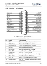
Page 40: ...ve 2 HEAD 0 Output Headset Speaker Positive 3 GND HEAD 0 Output Headset Speaker Negative 4 EXT NF Input external Audio Signal 5 MIC R DYN Input Microphone Right Dynamic 6 MIC L GND Input Microphone Left Ground 7 INTERCOM SWITCH Intercom Activation Switch connect to ground for Intercom activation 8 MIC L DYN Input Microphone Left Dynamic 9 DATA RX RS232 Receive for Remote Control 10 do not connect ...

Page 41: ...ect to ground for transmitting 16 LSP Output external Loudspeaker Negative Not identical to ground 17 PTT 1 Push to Talk 1 connect to ground for transmitting 18 MIC R STD Input Microphone Right Headset 19 MIC L STD Input Microphone Left Headset 20 HEAD 1 Output 1 Headset Speaker Positive 21 GND HEAD 1 Output 1 Headset Speaker Negative 22 DATA TX RS232 TX for Remote Control 23 N A do not connect 24...

Page 42: ...ion of the cable variants such as the corresponding cable diagram in document Doc No 01 14x 050 50 on our homepage under www funkeavionics de Service info download radios 4 7 3 2 Connector D SUB DE 9 Female for Remote Control This connector contains the serial interface and the power supplies for the remote control unit The remote control interface is a serial RX TX interface with RS232 voltage le...

Page 43: ... corresponds to 0 990 kHz The standby frequency and the active frequency can also be adjusted by Garmin devices The protocol corresponds to the Garmin SL40 4 7 3 3 Connector EXT NF for Monaural Audio Input This connector is used for the input of monaural audio signals He can be used e g for acoustic traffic warnings for radio navigation receiver s acoustic identifiers or for input of music into th...

Page 44: ... For glider installation the internal antenna installed by the manufacturer should be used The SWR shall not exceed 3 1 4 9 Microphone Intercom settings The settings of MIC and VOX values are essential for Intercom The respective configuration options are described in chapter 0 VOX threshold level and chapter 3 6 MIC input sensitivity If the VOX automatism is deactivated with VOX OFF intercom is a...

Page 45: ...ll not exceed 3 1 Furthermore a test flight is recommended in order to guarantee the proper in flight operation of the radio In a flight altitude of at least 2000 ft contact a ground station in a distance of at least 50 km 30 nautical miles Pay attention to unusual electrical interference If possible perform the radio test on frequencies within the upper and lower VHF communication frequency range...

Page 46: ...xx Operation and Installation Doc No 01 143A 010 71e Revision 1 00 46 4 11 Drawings 4 11 1 Dimensions The D Sub Connector plug has to be clamped with both spring locks It is recommended to additionally secure them with a cable tie ...

Page 47: ...1e Revision 1 00 4 11 2 Mounting Advices Panel cut out 160x42mm rectangular transversely aligned within view and reach of the pilot Attachment directly to the instrument panel using parts from mounting set MB800A2 scope of delivery Mount the two standard mounting blocks as indicated ...

Page 48: ...equency MHz Channel Width kHz Displayed Frequency in 8 33 25 kHz Mode Displayed Frequency in 25 kHz Mode 118 0000 25 118 000 118 000 118 0000 8 33 118 005 118 0083 8 33 118 010 118 0166 8 33 118 015 118 0250 25 118 025 118 025 118 0250 8 33 118 030 118 0333 8 33 118 035 118 0416 8 33 118 040 118 0500 25 118 050 118 050 118 0500 8 33 118 055 118 0583 8 33 118 060 118 0666 8 33 118 065 118 0750 25 1...

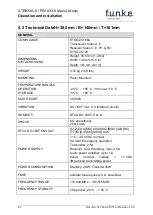
Page 49: ...ORAGE 20 C 55 C 30 min at 70 C 55 C 85 C MAX HEIGHT 35 000ft VIBRATION DO 160F Cat S Vibration Curve M HUMIDITY RTCA DO 160F Cat A SHOCK 6 G operational 20 G crash RTCA DO 160F ENV CAT C1Z CAA SM XXXXXXZ B XX AB BC TT M XXXXX XXXX XAC POWER SUPPLY 11 0 30 0 VDC nominal 9 0 VDC Emergency operation Transmitter 2 5A Receiver 0 2A Standby max 0 5A Audio power amplifier up to 1A below nominal voltage 1...

Page 50: ...NT 60dBc MODULATIONFIDELITY Deviation 6dB von 350 2500kHz CARRIER NOISE LEVEL 35dB at 70 modulation UNWANTED FREQUENCY MODULATION 1kHz at m 70 1kHz DUTY CYCLE capable of continuous transmission automatic interrupt after 35 seconds RECEIVER SENSITIVITY 105 dBm 6 dB S N N m 30 1 kHz BANDWIDTH 25 kHz 6 dB bandwidth 8 0 kHz BANDWIDTH 8 33 kHz 6 dB bandwidth 2 78 kHz SELECTIVITY channel spacing 25 kHz ...

Page 51: ... COOLING 4 5 4 Z No auxiliary cooling required ALTITUDE 4 6 1 C1 35 000 ft TEMPERATURE VARIATION 5 0 C 2 C change rate minimum per minute HUMIDITY 6 0 A SHOCK 7 0 B 6 G operational shocks 11ms 20 G Crash Safety Test Type R in all 6 directions 11ms VIBRATION 8 0 S Vibration Curve M EXPLOSION PROOFNESS 9 0 X No test required WATER PROOFNESS 10 0 X No test required FLUIDS SUSCEPTIBILITIES 11 0 X No t...

Page 52: ...UENCY CONDUCTED SUSCEPTIBILITY 18 0 B INDUCED SIGNAL SUSCEPTIBILITY 19 0 AC RADIO FREQUENCY SUSCEPTIBILITY 20 0 T EMISSION OF RF ENERGY 21 0 M LIGHTNING INDUCED TRANSIENT SUSCEPTIBILITY 22 0 X No ED23 test not required LIGHTNING DIRECT EFFECTS 23 0 X No test required ICING 24 0 X No test required ELECTROSTATIC DISCHARGE ESD 25 0 A FIRE FLAMMABILITY 26 0 C ...

Page 53: ...ATR833A II P N 833 II Axxx Axxx Operation and Installation 53 Doc No 01 143A 010 71e Revision 1 00 Notes ...

Page 54: ... fabrication utilities network know how engineering f u n k e AVIONICS GmbH Heinz Strachowitz Str 4 DE 86807 Buchloe Germany phone 49 8241 80066 0 fax 49 8241 80066 99 E mail service funkeavionics de www funkeavionics de ...

Reviews: