background image

TP Receivers • Installation and Operation

TP Receivers • Installation and Operation

Installation and Operation, cont’d

2-6

2-7

1

.

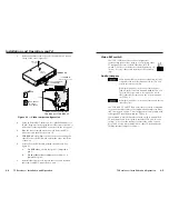
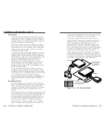
Remove the three screws on each side and the one or two
screws on top of the cover (figure 2-2).

J10
J11

J11

J10

AV board in TPR BNC AV

or

TP R AV

Wire Pair

3&6*

Wire Pair

7&8

Wire Pair

3&6*

*  TPX Compatible

Wire Pair

7&8

TP R AV
or
TP R BNC AV

Remove (7)

Screws

A

A-

OU

TP

UT

L

R

B

A-V

 IN

PU

T

VI

DE

O

AU

DI

O

PO

W

ER

15V .5A DC

L

R

Remove 1 (TP R AV) or
6 (TP R BNC AV)
BNC Hex Nuts

Lift Cover
straight up

1

1

1

1

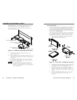
Figure 2-2 — Audio jumper configuration

2

.

Using an Extron BNC extraction tool (part #100-096-01) or a
14 mm, deep well socket with thin walls, remove the one or
six hex nuts securing the BNC connectors to the rear panel.

3

.

Slide the cover forward until the cover clears the BNC
connectors and then lift the cover off.

4

.

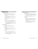
Locate J10 and J11 on the composite video printed circuit
board.  See figure 2-2.

a

.

For compatibility with redesigned (modified)
receivers and the TPX 88 A

, ensure that pin 1 is

jumpered to pin 2 on both jumper locations.

b

.

For compatibility with older (unmodified)
receivers

, ensure that pin 2 is jumpered to pin 3 on

both jumper locations.

5

.

Replace the cover, and reinstall the screws and BNC
connector hex nut(s).

Mounting the receiver

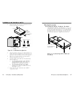
Rack mounting (TP R BNC A, TP R BNC AV, TP R 15HD A)

TP R BNC A, TP R BNC AV, or TP R 15HD AV

 — For optional

rack mounting, mount the receiver on a 19" 1U Universal Rack
Shelf (Extron part #60-190-01) (figure 2-3).  The TP R BNC A and
TP R BNC AV mount on the left or right side of the rack.  The
TP R 15HD A mounts in one of eight locations on the rack.

TP

 R 1

5H

D A

RG

B

PE

AK

IN

G

LE

VE

L

TP

 R 1

5H

D A

RG

B

PE

AK

IN

G

LE

VE

L

TP

 R 1

5H

D A

RG

B

PEA

KIN

G

LE

VE

L

TP R BNC A

V

VID

EO

MA

NU

AL

AU

TO

LEV

EL

PEA

KIN

G

RG

B

MA

NU

AL

AU

TO

LEV

EL

PEA

KIN

G

(2) 4-40 x 3/16" Screws

Use 2 Mounting Holes on
Opposite Corners

Figure 2-3 — Rack mounting the TP R 15HD A and
TP R BNC AV

Summary of Contents for TP R 15 HD A

Page 1: ...uilding Singapore 368363 65 6383 4400 Fax 65 6383 4664 Extron Electronics Japan Daisan DMJ Building 6F 3 9 1 Kudan Minami Chiyoda ku Tokyo 102 0074 Japan 81 3 3511 7655 Fax 81 3 3511 7656 www extron c...

Page 2: ...artung Alle Wartungsma nahmen sollten nur von qualifiziertem Servicepersonal durchgef hrt werden Die internen Komponenten des Ger tes sind wartungsfrei Zur Vermeidung eines elektrischen Schocks versuc...

Page 3: ...7 Rack mounting TP R BNC A TP R BNC AV TP R 15HD A 2 7 Furniture mounting 2 9 Projector mounting 2 10 Rear panel features and cabling 2 11 Transmitted signal cabling 2 11 Output cabling 2 12 Computer...

Page 4: ...tion About the TP Receivers Features Appendix Specifications Accessories and Part Numbers A 1 Specifications A 2 Included Parts A 5 Accessories A 6 Cables Adapters A 6 68 547 02 Rev G Printed in the U...

Page 5: ...1024 x 768 300 feet 1280 x 1024 200 feet 1600 x 1280 100 feet Recommended transmission ranges at 60 Hz all others Video format Maximum range Composite video and audio 1000 feet Component video and S v...

Page 6: ...s composite video on one BNC connector RJ 45 connector Allows attachment to an Extron TP transmitter Cable length compensation Allows you to select whether to compensate for long cable runs automatica...

Page 7: ...vers Introduction Introduction cont d TP Receivers 2 Chapter Two Installation and Operation Installation Overview Front Panel Controls and Indicators Troubleshooting 1 6 This page was intentionally le...

Page 8: ...he cable s between the TP transmitter s and the receiver See Transmitted signal cabling in this chapter and refer to the TP Transmitters Family User s Manual part 68 546 01 6 Connect the output cables...

Page 9: ...that pin 1 is jumpered to pin 2 6 Reinstall the video board replace the cover and reinstall the screws and BNC connector hex nuts Video DIP switch The TP R 15HD A receiver can be configured to receiv...

Page 10: ...n the composite video printed circuit board See figure 2 2 a For compatibility with redesigned modified receivers and the TPX 88 A ensure that pin 1 is jumpered to pin 2 on both jumper locations b For...

Page 11: ...helf Furniture mounting All of the receiver models can be mounted under furniture such as a table or podium surface using the appropriate optional mounting bracket Extron s Mini Under Desk Mounting Ki...

Page 12: ...other models Secure the receiver to a projector mount or other surface by inserting the mounting bolt through the bracket s slotted hole figure 2 6 A A V OUTPUT OUTPUT POWER 15V 5A DC L R B AV INPUT V...

Page 13: ...site video use the R G and or B BNC R or or G B H HV V The H HV and V BNCs only output sync not video signals 4 RGB Output 15HD TP R 15HD A Connect the desired video output device to the rear panel ou...

Page 14: ...ord into this connector to connect the TP R BNC AV to a 100 to 240VAC 50 Hz or 60 Hz power source If the distance between the transmitter and receiver is too great for the receiver to power the transm...

Page 15: ...AT 5e cable in A V applications The design of Extron s skew free A V UTP cable minimizes pair skew to the point that equalization is not required Skew exists between pairs when the physical length of...

Page 16: ...Auto position the receiver automatically adjusts the level and peaking to compensate for long cable runs In the Manual position you can manually compensate for long cable runs using the level and pea...

Page 17: ...off the edge of the screen adjust the transmitter s H Shift control DDSP disables the horizontal shift control 3 Place the receiver s Manual Auto switch to manual and adjust the level and peaking cont...

Page 18: ...nnectors 1 or 2 shielded RJ 45 female Frequency response 20 Hz to 20 kHz 0 05dB THD Noise 0 03 1 kHz 0 3 20 kHz at rated maximum output drive S N 63dB at nominal level Crosstalk 80dB 1 kHz fully loade...

Page 19: ...t weight TP R BNC A 1 6 lbs 0 7 kg TP R BNC AV 2 6 lbs 1 2 kg TP R 15HD A 0 4 lbs 0 2 kg TP R AV 0 9 lbs 0 4 kg Shipping weight TP R BNC A 4 lbs 1 8 kg TP R BNC AV 5 lbs 2 3 kg TP R 15HD A 2 lbs 0 9 k...

Page 20: ...Free Plenum 26 570 04 35 Skew Free Plenum 26 570 05 50 Skew Free Plenum 26 570 06 75 Skew Free Plenum 26 570 07 100 Skew Free Plenum 26 570 08 Skew Free A V cable RJ 45 jacks Part number 150 Skew Free...

Page 21: ...TP Receivers Specifications Accessories and Part Numbers Specifications Accessories and Part Numbers cont d A 8 This page was intentionally left blank...

Reviews: