background image

1. 

Select the video input by pressing the appropriate button (

HDMI

 or 

XTP

).

The EDID information is shown in a read-only panel.

2. 

To adjust 

Brightness

Contrast

Detail

, or 

Overscan

, press the appropriate button. A 

small window opens to the right of the screen. For 

Brightness

Contrast

, and 

Detail

the window shows the current value with right and left arrows to increment or decrement the 
value. To change the value more quickly, use the slider underneath.
To reset the value to default, press the default value. The default value for 

Brightness

Contrast

, and 

Detail

 is 

64

. All three parameters can be adjusted to any value between 

1


and 

127

.

3. 

Press 

Overscan

. A small window opens offering the options 

0%

2.5%

, and 

5%

. The default 

setting is 

5%

.

4. 

Press 

Exit

 to save the changes and return to the 

Input

 screen. 

Advanced Screen

Status

Display

Audio

Input

Advanced

Exit

Network

Menu Pin

Communication LED

System

GUI Project

Touchpanel Name:

Controller Name:

TLPPro1220_ABCDEF

IPCPPro350_FEDCBA

Controller IP:

192.168.254.250

------------------------------

Global Configurator Project

Name:

Version:

Creation Date:

Revision Date:

N_Campus.gcpro

0.0.22.0

6/22/2015 2:15:26 PM

6/25/2015 1:47:18 PM

Name:

Resolution:

Creation Date:

Revision Date:

N_Campus.gdl

1280x800

6/26/2015 11:31:55 AM

6/27/2015 12:06:31 PM

Version:

0.0.9

Project Size:

Storage Size:

Project Usage:

3 MB

196 MB

2%

On

Off

Change

Enable

Disable

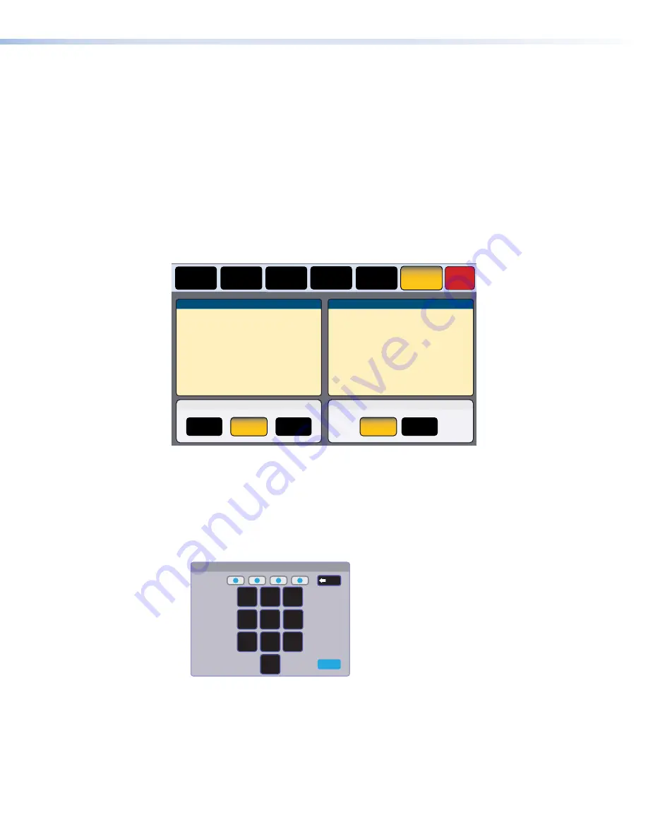
Figure 15. 

Advanced Screen

The System and GUI Project panels are read only, providing information about the system.

Menu PIN

Press 

Change

 to open the 

PIN


Setup

 window. The PIN setup options allow you to enable, 

disable, or change the setup menu PIN. The PIN is a 4-digit number. Each digit can have any 
value from 

0

-

9

.

1. 

Press a number on the keypad. A blue circle appears in the first box.

Enter New Menu PIN

4

5

6

7

8

9

0

2

1

3

Cancel

Back

Figure 16. 

Numeric Keypad for Setting PIN

2. 

Select the other three digits for the PINs. The fourth circle appears momentarily and then the 
screen changes to 

Confirm


New


Menu


Pin

.

3. 

Enter the PIN a second time. When the PIN entered on the second occasion matches the 
PIN entered on the first occasion, the PIN is set and the dialog closes.

Communication LED

The LED (see 

figure 2

A

 on page 6) can be enabled or disabled.


TLP Pro 1220, TLP Pro 1520, and TLP Pro 1720 Series • Setup Menu

19

Summary of Contents for TLP Pro 1220MG

Page 1: ...68 2294 01 Rev D 01 19 TLP Pro 1220 TLP Pro 1520 and TLP Pro 1720 Series User Guide TouchLink Pro Touchpanels TouchLink Pro Touchpanel Control Systems ...

Page 2: ...ent dans la documentation fournie avec le matériel Pour en savoir plus sur les règles de sécurité la conformité à la réglementation la compatibilité EMI EMF l accessibilité et autres sujets connexes lisez les informations de sécurité et de conformité Extron réf 68 290 01 sur le site Extron www extron com Istruzioni di sicurezza Italiano AVVERTENZA Il simbolo D se usato sul prodotto serve ad avvert...

Page 3: ...stems Inc or Extron Electronics see the current list of trademarks on the Terms of Use page at www extron com Registered Trademarks Cable Cubby ControlScript CrossPoint DTP eBUS EDID Manager EDID Minder Extron Flat Field FlexOS Glitch Free Global Configurator Global Scripter GlobalViewer Hideaway HyperLane IP Intercom IP Link Key Minder LinkLicense LockIt MediaLink MediaPort NetPA PlenumVault Pole...

Page 4: ...t was tested with shielded I O cables on the peripheral devices Shielded cables must be used to ensure compliance with FCC emissions limits For more information on safety guidelines regulatory compliances EMI EMF compatibility accessibility and related topics see the Extron Safety and Regulatory Compliance Guide on the Extron website Battery Notice This product contains a battery Do not open the u...

Page 5: ...computer or device responses mentioned in this guide the character 0 is used for the number zero and O represents the capital letter o Computer responses and directory paths that do not have variables are written in the font shown here Reply from 208 132 180 48 bytes 32 times 2ms TTL 32 C Program Files Extron Variables are written in slanted form as shown here ping xxx xxx xxx xxx t SOH R Data STX...

Page 6: ......

Page 7: ...er Global Configurator and Toolbelt 21 Using the Software 22 TLP Pro 1220 1520 and 1720 Series Web Page 22 Updating the Firmware 23 Downloading Firmware 23 Updating Firmware Using the Touchpanel Web Page 23 Updating Firmware Using Toolbelt 23 Mounting 24 Mounting the TLP Pro 1220MG 1520MG and 1720MG 24 Rack Mounting 24 Wall Mounting 25 Mounting the TLP Pro 1220TG 1520TG and 1720TG 28 Removing the ...

Page 8: ...TLP Pro 1220 TLP Pro 1520 and TLP Pro 1720 Series Contents viii ...

Page 9: ...0 Series touchpanels have 15 6 inch screens with a resolution of 1366x768 The TLP Pro 1720 Series touchpanels have 17 3 inch screens with a resolution of 1920x1080 The MG models TLP Pro 1220MG TLP Pro 1520MG and TLP Pro 1720MG are wall mountable The TG models TLP Pro 1220TG TLP Pro 1520TG and TLP Pro 1720TG have a weighted base that can be tilted which allows them to stand on any suitable table or...

Page 10: ...tus of a room System connection status indicator The communication LED provides visual feedback if the touchpanel is not communicating with a control processor Two high speed USB 2 0 ports For future expansion Automatic clock synchronization Allows touchpanel to display the accurate time and date Energy saving features Adjustable sleep timer puts touchpanel into sleep mode Motion detector wakes to...

Page 11: ...ron IPCP Pro 250 IP Link Pro Control Processor PC IR RS 232 HDMI HDMI HDMI Ethernet Ethernet Ethernet Power Extron TLP Pro 1220MG 12 Wall Mount TouchLink Pro Touchpanel Extron HDMI DA2 Distribution Amplifier Motion Sensor Power Injector Figure 1 Application Diagram Requirements Software For a complete list of the requirements for running GUI Designer Global Configurator Plus and Professional and T...

Page 12: ...assword By default this is extron for either admin or user MAC address Make a note of the touchpanel MAC address which can be found on the rear panel label you need to remove the back cover for TG models 3 Mount and cable the units ATTENTION Do not power on the touchpanels or control processors until you have read the Attention notice on page 11 12 VDC power supply or on page 10 power injector Ne ...

Page 13: ...IP address subnet mask gateway and related settings for the touchpanel 5 Configure the Touchpanels the GUI Designer Help File the Global Configurator Help File and the Toolbelt Help File provide step by step instructions and detailed information The Global Configurator Help File also includes an introduction to that software and sections on how to start a project and configuration TLP Pro 1220 TLP...

Page 14: ... 1220MG and 1520MG models are very similar to the TLP Pro 1720MG and the features of TLP Pro 1220TG and 1520TG models are very similar to the TLP Pro 1720TG A A B B C C D D E E E E F F G G A A B B C C D D E E F F E E Figure 2 TLP Pro 1720MG Left and TLP Pro 1720TG Right Front Panels A Communication LED B Status light C Ambient light sensor D Capacitive touch screen E Speakers 2 F Motion sensor G M...

Page 15: ... monitors ambient light level and adjusts screen brightness based on the settings configured using the Setup Menu D Capacitive touch screen with a touch overlay The touchpanel has a resolution of 1280x800 TLP Pro 1220 series 1366x768 TLP Pro 1520 series or 1920x1080 TLP Pro 1720 series E Speakers two speakers located below the screen one on each side of the panel provide stereo audio for video pre...

Page 16: ...ED indicates power status and reset status of the device see Reset Modes on page 30 B Reset button initiates one of three reset modes for the unit see Reset Modes C Menu button activates the Setup Menu see page 13 D USB connectors two high speed USB 2 0 connectors for peripheral controls E Audio output a 3 5 mm headphone jack provides local line level audio output from the touchpanel F XTP PoE LAN...

Page 17: ...nclude patch points punch down connectors couplers and power injectors If these pass through points are required use shielded couplers and punch down connectors NOTES When using shielded twisted pair cable in bundles or conduits consider the following Do not exceed 40 fill capacity in conduits Do not comb the cable for the first 20 meters where cables are straightened aligned and secured in tight ...

Page 18: ... indoor use only It is to be connected only to networks or circuits that are not routed to the outside plant or building L alimentation via Ethernet PoE est destinée à une utilisation en intérieur uniquement Elle doit être connectée seulement à des réseaux ou des circuits qui ne sont pas routés au réseau ou au bâtiment extérieur The touchpanels are intended for connection to a Power over Ethernet ...

Page 19: ... within the dedicated closet podium or desk Sauf mention contraire les adaptateurs AC DC ne sont pas appropriés pour une utilisation dans les espaces d aération ou dans les cavités murales La source d alimentation doit être située à proximité de l équipement de traitement audiovisuel dans un endroit ordinaire avec un degré 2 de pollution fixé à un équipement de rack à l intérieur d un placard d un...

Page 20: ...es 2 TG models only Secure the base to the touchpanel For VESA Mounting remove the base by unscrewing the hinges Routing Cables TG Models Organize cables behind the rear and base covers for a more esthetically appealing appearance The TLP Pro 1520TG is shown below but the TLP Pro 1220TG and TLP Pro 1720TG are similar A A B B C C C C D D Figure 5 TLP Pro 1520TG Cable Organization 1 If necessary rem...

Page 21: ... small screwdriver to press the button The menus open at the Status screen There are six different buttons in the navigation panel at the top of the screen These open the following screens Status Screen see the following page Network Screen see the following page Display Screen see page 16 Audio Screen see page 17 Input Screen see page 17 Advanced Screen see page 19 The button for the selected scr...

Page 22: ...ork connection The red square shown in the Advanced panel indicates that no control processor is connected Network Screen The Network screen allows you to set the DHCP status and if DHCP is set to Off the network addresses for the touchpanel Verify with your network administrator whether the IP address for the touchpanel is assigned by DHCP or set manually If it is set manually you need to obtain ...

Page 23: ...he old address If you start typing without pressing Clear the first octet is over written and the other octets remain the same c Press any octet button to highlight and start editing it d Enter the 3 digit value for that octet leading zeroes in the octet are ignored NOTE Octets can have any value between 0 and 255 You cannot enter an invalid number For example if you try to enter 892 you are able ...

Page 24: ...ws you to set the Sleep Timer Auto Brightness LCD Brightness and Wake on Motion Sleep Timer determines how long the panel is inactive before it enters sleep mode when the screen goes dark to save power Select either On or Off If the sleep timer is On use the arrows to adjust the value between 1 and 120 minutes Auto Brightness provides a suitable amount of backlighting that is automatically calcula...

Page 25: ... audio file playback HDMI sets the volume of the HDMI input XTP sets the volume of the XTP input Click on the speaker and headphones icon at the bottom of each panel to toggle between audio on and audio mute The Sound audio is muted in figure 11 Input Screen Input Configuration Input Status Native Display 1280x800 50 Hz HDMI LPCM 2Ch Extron HDMI XTP Signal 1920x1080 59 94 EDID 1280x800 50 Hz Signa...

Page 26: ...nd refresh rate The button is black if the native display is used and turns yellow if you are setting the EDID manually Pressing the button opens the EDID Minder window When setting the EDID manually only the Resolution panel is initially populated Once the resolution is selected the available refresh rates for that resolution are displayed When both the resolution and refresh rate are selected pr...

Page 27: ...t Name Version Creation Date Revision Date N_Campus gcpro 0 0 22 0 6 22 2015 2 15 26 PM 6 25 2015 1 47 18 PM Name Resolution Creation Date Revision Date N_Campus gdl 1280x800 6 26 2015 11 31 55 AM 6 27 2015 12 06 31 PM Version 0 0 9 Project Size Storage Size Project Usage 3 MB 196 MB 2 On Off Change Enable Disable Figure 15 Advanced Screen The System and GUI Project panels are read only providing ...

Page 28: ...n text and graphics using GUI Designer which is a Windows based application You can either customize an existing template or create an entirely new interface GUI Designer offers several templates 2 After the user interface has been designed the project is saved built and imported into Global Configurator Plus and Professional 3 Use Global Configurator Plus and Professional to assign functions to t...

Page 29: ...available on the Software home page scroll down the page to the alphabetic menu bar and click on the appropriate initial letter NOTE If you select Global Configurator Plus and Professional there is a check box that allows you to download Toolbelt at the same time 4 If necessary scroll down the list of options to the desired software 5 Click the Download button next to the program and follow the on...

Page 30: ...1720 Series Web Page To access the touchpanel default web page enter the IP address of the unit into the web browser of a PC connected to the same subnet A dialog opens asking for your user name and password By default the user name is admin and the password is extron both user name and password are all lower case There is a single page most of which is read only providing general and network info...

Page 31: ...ed information and press the download button An executable exe file is downloaded to your computer Run this program to place the firmware on your computer for future use Make a note of the folder where the firmware is saved Updating Firmware Using the Touchpanel Web Page 1 If you have not already done so download the firmware file to a computer on the same network as the touchpanel see the previou...

Page 32: ...ulti unit rack assembly the operating ambient temperature of the rack environment may be greater than room ambient temperature Therefore install the equipment in an environment compatible with the maximum ambient temperature Tma 104 F 40 C specified by Extron Reduced air flow Install the equipment in the rack so that the equipment gets adequate air flow for safe operation Mechanical loading Mount ...

Page 33: ...stallation must be performed by qualified personnel in accordance with local and national building codes and electrical codes Toute étape structurelle et installation électrique doit être effectuée par un personnel qualifié conformément aux codes du bâtiment aux codes incendie et sécurité et aux codes électriques locaux et nationaux Some local building codes require the touchpanel to be mounted in...

Page 34: ...e purchased separately as described in the BB 700M Installation Guide see www extron com 2 Place the metal mounting plate against the wall mark the four mounting holes and drill four pilot holes 3 Secure the mounting plate with four 10 screws 4 Run and connect cables to the rear of the touchpanel see TLP Pro 1220 1520 and 1720 Series Rear Panel Features on page 8 5 Insert the two provided Phillips...

Page 35: ...e hole and drill the four pilot holes The size of the cut out hole is 9 25 inches 23 50 cm wide x 6 25 inches 15 88 cm high for the TLP Pro 1220MG 1520MG and 1720MG 3 Secure the mounting plate and complete the installation as described in steps 3 8 on the previous page Use cut out template to cut hole in the wall 1 1 Secure mounting plate to the wall 3 3 Figure 22 Mounting Without a Wall Box TLP P...

Page 36: ...ounting The TLP Pro 1220TG TLP Pro 1520TG and TLP Pro 1720TG come assembled with stands that allow the units to be placed on any suitable flat surface for example a desk table or lectern Placement without a Mounting Kit Figure 24 shows the base of the TLP Pro 1220TG with the cover removed to indicate the position of the mounting holes The bases of the TLP Pro 1520 TG and TLP Pro 1720TG are similar...

Page 37: ...insulation disk and swivel disk and configure the set screws to allow for the degree of swivel that is required see the SMA 1 Swivel Mount Adapter Kit User Guide at www extron com 3 Place the mounting hole in the base over the conduit of the SMA 1 4 Secure the unit with the backing plate and locking nut as described in the SMA 1 Swivel Mount Adapter Kit User Guide VESA Mounting The TLP Pro 1220TG ...

Page 38: ...power cycle in the event of a firmware update that failed or incompatibility issues arising with user loaded firmware Activation 1 On the touchpanel hold down the recessed Reset button while applying power to the unit When power is restored the Reset LED lights Hold the Reset button for a further two seconds before releasing it The touchpanel enters factory firmware mode 2 Upload new firmware to t...

Page 39: ...P off Reset to Factory Defaults This mode resets all IP settings and touchpanel settings to factory defaults and removes all configurations It allows you to start over with configuration and uploading Activation To reset the unit to all factory default settings 1 Hold down the Reset button until the Reset LED blinks three times once at 3 seconds again at 6 seconds and again at 9 seconds 2 Release ...

Page 40: ...ty does not apply if the fault has been caused by misuse improper handling care electrical or mechanical abuse abnormal operating conditions or if modifications were made to the product that were not authorized by Extron NOTE If a product is defective please call Extron and ask for an Application Engineer to receive an RA Return Authorization number This will begin the repair process USA 714 491 1...

Reviews: