


4
PVM 220 • Installation Guide (Continued)
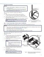
Step 5 — Run signal and control cables to the PVM 220.
Run the signal and control cables either into cable clamps or through
conduit attached to the PVM 220 enclosure (see figure 7).
To install a cable clamp on the enclosure:
a.
Select a suitable sized cable clamp for the quantity and
thickness of cable to be fed into the enclosure (see the
Notes
on page 3, Step 4 for knockout sizes).
b.
Identify the most suitable cable entry point and remove one
or more knockouts as needed.
NOTE:
Remove only the knockouts that are to be used for
cabling. Leave intact the unused knockouts.
c.
Remove the large nut from the back of the cable clamp and
insert the clamp into the enclosure knockout from the inside.
d.
Place the nut on the clamp and tighten to secure.
e.
Pass the cables through the clamp into the enclosure. Leave
enough cable slack at the PVM 220 to ensure cable connection
to any device is maintained when the access door is open.
f.
Tighten down the cable clamp until the cables are held firmly.
Avoid damaging or bending cables at too sharp an angle.
NOTE:
See the
PoleVault System Installation Guide
for full
cable connection details.
Step 6 — Install devices onto the device mounting plate.
NOTE:
The maximum door load is 15 lbs (6.8 kg).
To mount the devices and accessories:
a.
If mounting a PoleVault (PVS) switcher, carefully align the
switcher with the appropriate holes in the marked location on
the device mounting plate (the location is indicated by a white
device outline and 2 arrows, see figure 8).
Non-PVS devices can be mounted anywhere within the enclosure.
NOTE:
The PVS switcher must be mounted in the
designated area ONLY. This ensures that the switcher is
positioned correctly for proper ventilation.
b.
Secure the PVS switcher with the supplied #4-40,
3/16 inch
mounting screws, tightening each one until snug. Do not
overtighten.
c.
Align the power supply with the appropriate holes in the marked
location on the device mounting plate (location is indicated
by a white device outline and 3 arrows). Secure using the
supplied screws.
NOTE:
Replacement power supplies must be either the
equivalent Extron power supply, or a UL Listed NEC
Class 2 power supply.
d.
Mount all other devices following the procedures in the
supplied device guide.
PVS 4
05SA
IP
POLE
VAU
LT SW
ITCH
ER
INPU
TS
AUD
IO LE
VEL A
DJU
ST
PAGIN
G
SENS
OR
SEN
SITIV
ITY
PEA
K
NOR
MAL
SIGN
AL
VOICE
LIFT
PEA
K
NOR
MAL
SIGN
AL
INPU
T
SELEC
T
CON
FIG
R
1
2
3
4
5
A
U
X
A
U
D
IO
E
Mount the PoleVault
switcher with the front
panel facing outwards
in the marked location.
Mount other optional
devices as desired.
Mount the PoleVault
Switcher Power Supply
in the marked location.
Device
Mounting Plate
ò
ô
õ
Figure 8.
PVS Switcher and Power Supply Mounting
Locations on Device Mounting Plate.
ì
Push the cable clamp into the
knockout from inside the enclosure.
í
Attach the nut from the outside
of the enclosure.
Figure 7.
Install a cable clamp on the PVM 220
enclosure (viewed from above).
POWER
SUPPLY
POLEVAULT SWITCHER
Figure 9.
Install the devices onto the mounting plate.