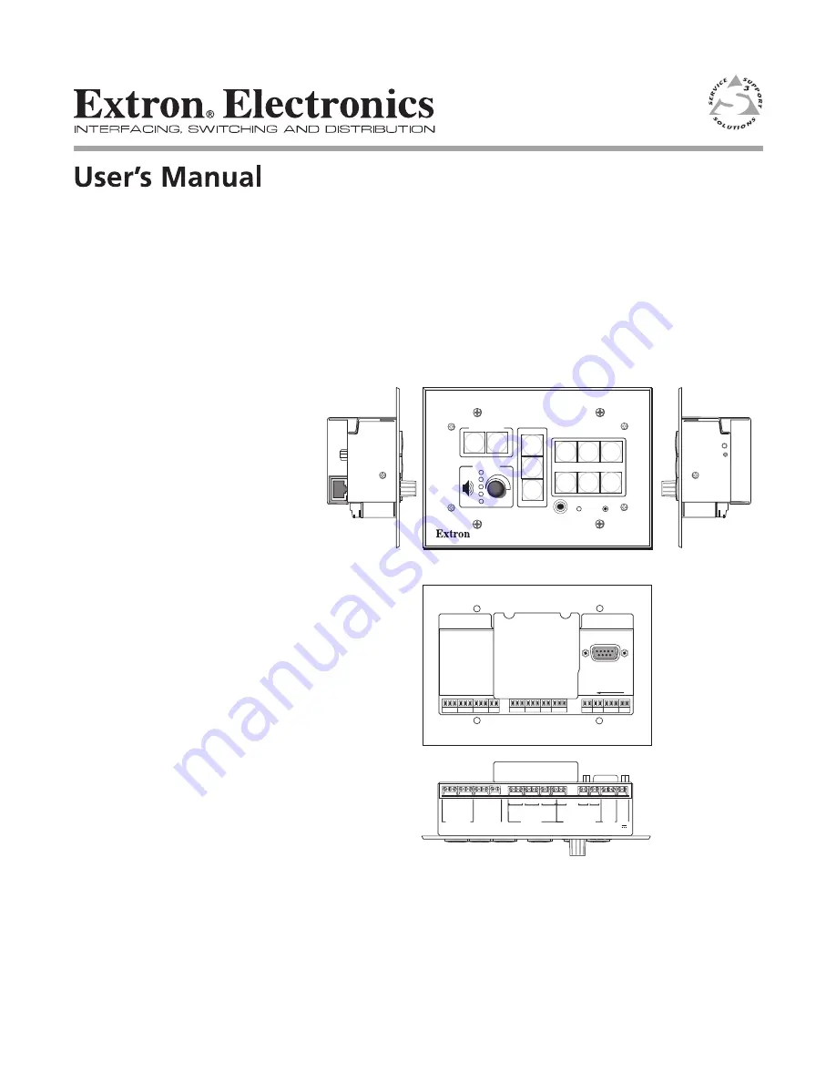
background image

MLC 226 Series

MediaLink

 Controllers

68-955-01  

Rev. A

11 04

Check the Extron Web site (

www.extron.com

) for updates.

PRELIMINARY

HOST

CONTROL

R

1=D INPUT   2=Tx   3=Rx

5=GND, 38400, N, 8, 1

PRESS TAB WITH

TWEEKER TO REMOVE

PROJECTOR

RS-232/IR

RS-232  12V

CM/ IR SCP

A   B   C   D   E

C   1   2

A

RELAYS

IR/SERIAL OUT

MLS   PWR

C   3   4

B

C   5   6

C

S   G

A

S   G

B

A B

S   G

C

Tx/IR

Rx

GR

OUND

PWR SNS

GR

OUND

+12V OUT

Rx

Tx

GR

OUND

GR

OUND

+12V IN

+12V OUT

GR

OUND

CONT MOD

IR IN

SCP COM

LAN

PROJECTOR

MLC 226 IP

1

2

3

4

5

6

VOLUME

CONFIG

IR

ON

OFF

LIGHT

ON

LIGHT

OFF

LAPTOP

VCR

DVD

PC

AUX

VIDEO

LECTERN

PC

AUTO

IMAGE

Front

Rear

Right Side

Left Side

Bottom 

(rotated 180 degrees)

Summary of Contents for MLC 226 Series

Page 1: ...JECTOR RS 232 IR RS 232 12V CM IR SCP A B C D E C 1 2 A RELAYS IR SERIAL OUT MLS PWR C 3 4 B C 5 6 C S G A S G B A B S G C Tx IR Rx GROUND PWR SNS GROUND 12V OUT Rx Tx GROUND GROUND 12V IN 12V OUT GROUND CONT MOD IR IN SCP COM LAN PROJECTOR MLC 226 IP 1 2 3 4 5 6 VOLUME CONFIG IR ON OFF LIGHT ON LIGHT OFF LAPTOP VCR DVD PC AUX VIDEO LECTERN PC AUTO IMAGE Front Rear Right Side Left Side Bottom rota...

Page 2: ...rksam machen daß im Inneren des Gehäuses dieses Produktes gefährliche Spannungen die nicht isoliert sind und die einen elektrischen Schock verursachen können herrschen Achtung Lesen der Anleitungen Bevor Sie das Gerät zum ersten Mal verwenden sollten Sie alle Sicherheits und Bedienungsanleitungen genau durchlesen und verstehen Aufbewahren der Anleitungen Die Hinweise zur elektrischen Sicherheit de...

Page 3: ...guide 2 13 Mounting the MLC 2 13 Mounting the MLC to an electrical box or mud ring 2 14 Mounting the MLC to a wall or furniture 2 15 Rack mounting an MLC 226 IP L 2 15 Mounting the MLC in a Euro Channel 2 16 Chapter 3 Front Panel Features and Basic Operation 3 1 Projector Control 3 2 Front Panel Features and Operation 3 2 Buttons 3 2 Volume control 3 4 IR signal sensors 3 4 Configuration port 3 5 ...

Page 4: ...onfiguration 4 13 IR learning creating a customized IR driver file 4 13 Enabling disabling switcher slaving 4 18 Updating MLC 226 IP firmware 4 19 Performing a master reset 4 19 Enabling disabling switcher slaving 4 19 Reflecting changes made via attached SCPs or control modules 4 19 Help menu 4 19 User Mode 4 20 Noteworthy features 4 21 Real Time Adjustments 4 22 Noteworthy features 4 23 RS 232 I...

Page 5: ... Reference Material A 1 Specifications A 2 Part Numbers and Accessories A 4 Included parts A 4 Accessories A 4 Cables A 6 Glossary A 7 68 955 01 Rev A Printed in the USA 11 04 All trademarks mentioned in this manual are the properties of their respective owners ...

Page 6: ...iv MLC 226 Series Table of Contents Table of Contents cont d PRELIMINARY ...

Page 7: ...MLC 226 MediaLink Controllers 1 Chapter One Introduction About the MLC 226 Series MediaLink Controllers How the MLC 226 Series Controllers Work MLC Components and Interactions ...

Page 8: ...s front panel controls Additional features for MLC 226 IP models Via Ethernet IP communication the MLC 226 IP models can make use of the controller s embedded Web pages which include online diagnostics and monitoring of basic control features As an integrated part of the MLC 226 IP IP Link provides the following advantages Global compatibility The switcher uses standard Ethernet communication prot...

Page 9: ...ediaLink Controller A typical application for an MLC 226IP MediaLink Controller How the MLC 226 Series Controllers Work MLC Components and Interactions Unlike the Extron MediaLink Controller MLC 206 Series the MLC 226 Series requires and uses event files to perform all functions except basic input switching and volume control The event files define monitor and govern how an MLC 226 Series controll...

Page 10: ...n is used to create the main event 0 evt script file that defines the MLC s operation The main event file also controls and monitors ports optional SCP control pad s and changes made at the MLC s front panel Each button on the MLC and on any connected SCPs control modules IRCMs ACMs RCMs or the IR 402 remote control has two switch numbers assigned to it one for the button press one for release Scr...

Page 11: ...k Controllers 2 Chapter Two Installation Labeling Cabling Mounting UL Safety Requirements Installing or Replacing Button Labels Panels and Cabling Side Panel Features Reset Button and LED Pinout Guide Mounting the MLC ...

Page 12: ...at any time Follow these steps to change the translucent button labels 1 Remove the button from the MLC or SCP use a small flat bladed screwdriver such as an Extron Tweeker to gently pry a button out from the front panel 2 Locate the notch in the corner of one side of the clear button cap 3 Separate the white backing from the clear button cap insert the blade of the small screwdriver into the corn...

Page 13: ... IP Rear Panel 1 Rear panel Host Control port For MLC configuration and control connect a Windows based PC or an RS 232 control system to the MLC via this female 9 pin HD connector This connector also has one pin designated for digital input output RS 232 protocol 38400 baud 1 stop bit no parity 8 data bits no flow control The pin assignments of this connector are as follows DB9 Pin Locations Fema...

Page 14: ... 5 mm stereo mini TRS RS 232 cable part 70 335 01 shown below can be used for this connection This port has the same protocol as the rear panel port mentioned above but does not offer digital input RS 232 protocol 38400 baud 1 stop bit no parity 8 data bits no flow control 6 feet 1 8 m Part 70 335 01 5 1 9 6 Sleeve Gnd Ring Tip 9 pin D Connection TRS Plug Pin 2 Computer s RX line Tip Pin 3 Compute...

Page 15: ...ble between the projector and the left three poles of this 3 5 mm direct insertion captive screw connector for RS 232 one or two way projector display control Alternatively the Tx IR and Ground pins can be used for one way infrared signal output From this port commands from a projector driver or user defined command strings entered via the Windows based configuration program can be sent to the dis...

Page 16: ...iring For details refer to the manual that came with the projector Maximum distances from the MLC to the device being controlled may vary up to 200 feet 61 m Factors such as cable gauge baud rates environment and output levels from the switcher and the device being controlled all affect transmission distance Distances of about 50 feet 15 m are typically not a problem In some cases the MLC may be c...

Page 17: ...N LIGHT OFF LAPTOP VCR DVD PC AUX VIDEO LECTERN PC AUTO IMAGE 200 61 m max The maximum total distance between the MLC 226 and a connected device is 200 61 m This port provides up to 12 VDC for powering the SCP control pad or other devices The automatic current protection circuit for this port limits the draw to 0 5 amperes If an IRCM RCM ACM is to be used in an MLC SCP system the control modules c...

Page 18: ...commands or the configuration software to operate as follows on relay closes and stays closed until otherwise instructed off relay opens and stays open until otherwise instructed toggle relay changes from open to closed or from closed to open until otherwise instructed pulse momentary timed press to turn on timeout to turn off On Closed Common Off Open Common Relay On Relay Off On Closed Common Of...

Page 19: ...lled may vary up to 200 feet 61 m Factors such as cable gauge baud rates environment and output levels from the MLC and the device being controlled all affect transmission distance Distances of about 50 feet 15 m are typically not a problem In some cases the MLC may be capable of transmitting and controlling a given device via RS 232 up to 250 feet 76 m away For infrared IR output 0 to 5 VDC wire ...

Page 20: ...T 2 VIDEO Y C R Y B Y INPUT 3 VIDEO Y C R Y B Y INPUT 4 R H HV G V B INPUT 5 R H HV G V B INPUT 6 R H HV G V B RGB R H HV G V B 4 ohm MONO AMPLIFIED OUTPUT COMM 8 ohm 70V L R L R L R L R AUX MIX EFFECTS L R SEND L R RETURN MLC IR RS232 CONTACT CLOSURE A B C AUDIO OUT FIXED VARIABLE L R L R L L R R L R MediaLink Switcher s rear panel MLC IR port NOTE You must connect a ground wire between the MLC a...

Page 21: ...ng basis to connect and to control the MLC 226 and the devices connected to it in an Ethernet network Plug a cable into this RJ 45 socket and connect the other end of the cable to a network switch hub router or PC connected to an Ethernet LAN or the Internet For 10Base T 10 Mbps networks use a Cat 3 or better cable For 100 Base T max 155 Mbps networks use a Cat 5 cable You will also need to config...

Page 22: ...three times once at 3 sec again at 6 sec again at 9 sec Then press Reset momentarily for 1 sec within 1 second The MLC reverts to the factory default firmware Event scripting will not start if the MLC is powered on in this mode All user files and settings drivers adjustments IP settings etc are maintained Mode 3 turns events on or off During resetting the Reset LED flashes 2 times if events are st...

Page 23: ...ive Rx Transmit Tx To a projector or display To an Extron Power Sensor OR 12 VDC Ground Power sense To an IR Emitter IR Broadcaster or IR or serial RS 232 controllable device Ground 12 VDC input SCP communication IR Modulated IR for IR Link Ground IRCM ACM RCM 12 VDC Digital input Ground Signal IR Mounting the MLC Once the system has been cabled configured see chapter four and tested the controlle...

Page 24: ...und and the circuit ground via a connector pin If you tie a product to two different ground sources you may introduce ground loops or other grounding related problems into the system For the installation to meet UL requirements and to comply with National Electrical Code NEC the MLC must be installed in a UL approved junction box The end user or installer must furnish the junction box it is not in...

Page 25: ...te earth ground and the circuit ground via a connector pin If you tie a product to two different ground sources you may introduce ground loops or other grounding related problems into the system For the installation to meet UL requirements and to comply with National Electrical Code NEC the MLC must be installed in a UL approved junction box The end user or installer must furnish the junction box ...

Page 26: ...sert the MLC into the Euro Channel For wider types of Euro Channels you may need to insert a spacer plate first 4 Mount the controller to the Euro Channel by attaching the faceplate to the two backing plates using four 4 40 mounting screws See the illustration below Make sure that the Euro Channel is grounded to an earth ground before completing the installation Extron MLC 226 EC Euro Channel Back...

Page 27: ...MLC 226 MediaLink Controllers 3 Chapter Three Front Panel Features and Basic Operation Projector Control Front Panel Features and Operation Front Panel Security Lockout Executive Modes ...

Page 28: ...ng or learning projector control commands Front Panel Features and Operation Many features must be set up in order for the MLC to function See chapter 4 Software and Web Page based Setup and Control for information about the MLC 226 104 Configuration Program which you must use to set up most features of the MLC PROJECTOR MLC 226 IP 1 2 3 4 5 6 VOLUME CONFIG IR ON OFF LIGHT ON LIGHT OFF LAPTOP VCR ...

Page 29: ...s in the room such as a projector lift screen motor or lighting For details on how the relays operate and can be configured see the installation instructions in chapter 2 and the configuration software information in chapter 4 2 Function room control buttons These have the same capabilities as the input selection buttons 3 but are typically used for triggering commands and functions other than inp...

Page 30: ...tandard Extron SIS commands sent via the MLS connector are fixed and cannot be altered The command for each input is shown at right Volume control 4 Volume knob and LEDs Rotate this knob to adjust the audio volume Volume can be adjusted via this front panel knob or via RS 232 Telnet Web browser control The included configuration software lets you select whether this knob will control the projector...

Page 31: ...ning via a front panel connection after the MLC has been installed Connect a Windows based PC or an RS 232 control system to this 2 5 mm mini stereo style tip ring sleeve connector You can use the Extron 9 pin D to 2 5 mm stereo mini TRS RS 232 cable part 70 335 01 or make your own cable See chapter 2 for a wiring diagram and port protocol This port requires 38400 baud communication a higher speed...

Page 32: ...tional IR 402 remote duplicate the MLC s front panel controls and also those of a VCR and a DVD player for normal operation The IR 402 can also be used to control a MediaLink Switcher The controller or switcher responds to commands from the IR 402 remote as if the corresponding button or knob were pressed or turned on the controller or switcher From a distance of no more than 30 feet and within 40...

Page 33: ...browser control The Simple Instruction Set SIS command 3X corresponds to this mode For details see chapters 4 and 5 Preparing the MLC for front panel lockout 1 Connect cables and power on the MLC and the host computer 2 Install and start the configuration software See chapter 4 3 Click on the Tools drop down menu and select PIN Manager 4 Click a radio button Admin PIN Enabled or Both PINs Enabled ...

Page 34: ... Panel of an MLC 226 Series Controller 1 1 2 If the incorrect PIN was entered no buttons flash the green Volume LEDs turn off and the red top LED blinks Then the buttons light as they were lit before front panel lockout was set Release all buttons If the correct PIN was entered the green Volume LEDs flash and all buttons flash green twice indicating that front panel is locked then return to the wa...

Page 35: ...6 MediaLink Controllers 4 Chapter Four Software and Web Page based Setup and Control Configuring the Hardware Configuration Software for Windows Embedded Web Pages Controlling the MLC 226 IP via Global Viewer ...

Page 36: ...se The MLC 226 104 Configuration Program automatically sets the connection for the appropriate speed If using HyperTerminal or a similar application make sure the PC or control system connected to these ports is set for 38400 baud MLC 226 s LAN port defaults MLC s IP address 192 168 254 254 Gateway s IP address 0 0 0 0 Subnet mask 255 255 0 0 DHCP off Link speed and duplex level autodetected An ML...

Page 37: ...6 IP for DHCP Dynamic Host Configuration Protocol to have an address assigned automatically when you sign on 1 Open the Network Connections page as follows Locate and right click on My Network Places on the Windows 2000 XP or higher desktop then click on Properties or Click on the Start menu click on Settings if needed click on Control Panel then double click on Network and Dial up Connections 2 R...

Page 38: ...sk 255 255 0 0 Default gateway blank or 0 0 0 0 c Click on the OK button to save the changes and exit the network setup Reboot the PC if required for the changes to become effective 6 Plug one end of a Category 5 network Ethernet crossover cable into the MLC s Ethernet LAN connector Refer to chapter two for RJ 45 LAN connector wiring Plug the other end of the Ethernet cable into the Ethernet port ...

Page 39: ... controller s MAC address with the assigned IP address You must then use the ping utility to access the controller at which point the controller s IP address is reconfigured Use ARP to configure the MLC 226 IP s IP address as follows 1 Obtain a valid IP address for the controller from your network administrator 2 Obtain the controller s MAC address UID from the label on its rear top or side panel ...

Page 40: ...le or arp d removes all static IP addresses from the ARP table 7 After configuring the controller remember to change your PC s TCP IP settings back to their original configuration Configuring the MLC via a Web browser The default Web pages that are preloaded on the MLC 226 IP are compatible with the Internet Explorer Web browser version 5 5 or higher 1 Obtain a valid IP address for the controller ...

Page 41: ...are installation 2 To run the program double click on the MLC Configuration Program icon in the Extron Electronics group or folder The COM port selection menu appears as shown at right 3 If the PC and controller are connected via RS 232 select the COM port to be used and click on OK The Extron MLC 226 104 Configuration Program window appears This method RS 232 is recommended in order to maintain t...

Page 42: ...ontrollers only but the device drivers for controlling projectors VCRs DVD players etc can be used by other Extron IP Link products so they may be listed as an IP Link driver file package 2 Follow the onscreen instructions to download and install both programs MLC 226 104 Configuration Program IR Learner and the driver package By default the installation creates an MLC 226 directory and it places ...

Page 43: ...r port and the four IR Serial Out ports then select the appropriate device driver for each port based on the device connected to the port Button Config is the tab for setting up every configurable button in the system MLC front panel Projector power function room and input selection buttons buttons on all connected control modules IRCMs ACMs RCMs and the buttons on the IR 402 remote control On thi...

Page 44: ... not found in other parts of the software File menu The File menu provides ways to access device driver and configuration files and to save a configuration for future use The File menu Adding a new device driver to the MLC 1 Select Import DRIVER from 2 Locate and select the driver file that is stored on the PC RS 232 driver files have filenames ending in pke and infrared driver filenames end in ei...

Page 45: ...uration file To retrieve a previously saved configuration select File then select Restore Button Driver Port CONFIGURATION from or Restore Full CONFIGURATION from Follow the onscreen directions A set of adjustment settings control commands drivers events and other settings is uploaded into the controller depending on which option you select Tools menu The Tools menu shown below gives you access to...

Page 46: ...buttons see pages 3 7 and 3 8 Before front panel lockout can be enabled via the MLC s buttons you must set up personal identification numbers and enable them Set up the PINs and unit access via the PIN Manager feature in the Tools drop down menu 1 Connect cables power on the MLC and the host computer and start the configuration software 2 Click on the Tools drop down menu and select PIN Manager A ...

Page 47: ...to rebuild a configuration unless you have changed the controller s settings drivers or event scripts If configuration changes have been made that require rewriting file settings a button should appear in the lower right of the configuration program window to let you update the configuration files and store them in the MLC If not you may use the Rebuild Apply Configuration option in the Tools menu...

Page 48: ...selected 2 If an active connection is already established between the controller and the PC skip to step 4 If not click on the Device Finder icon In the dialog box that pops up you can set select how to connect to the MLC via an IP connection TCP or via RS 232 Serial Then select the specific device or connection parameters For IP connection select the TCP tab shown at right and either select the M...

Page 49: ...ss privileges 3 Select Connect to accept the settings and make the connection to the MLC If you chose an IP connection the IP address is displayed in the connection information window If you selected an RS 232 connection the protocol is shown in the window Selecting OK instead of Connect accepts the settings but does not make the connection To establish a connection from the PC to the MLC after se...

Page 50: ...to the left of this information 6 In the list that appears in the left window click on a function or functions to be learned To select multiple functions from the list press and hold the control Ctrl key on the keyboard and click on the desired functions The blue arrows indicate functions that have not been learned or that have not been saved to the driver file If the Other category is selected fr...

Page 51: ...ng screen samples and the function s to be learned is are listed within that dialog box The example below shows how the screen looks when multiple functions have been selected 8 Click on the Learn button to start the IR learning process and follow the onscreen instructions During IR learning point the device s remote control at the IR learning receiver and keep it within about 12 30 cm of the port...

Page 52: ...uble click on it and enter the function s new name 12 To remove an unneeded function select that function from the list then click on the Unlearn Function button which resembles an eraser 13 Save the IR driver file Select Save from the File menu or click on the Save Driver button which looks likes a floppy disk Name the file use a name that reflects the device s model name then click Save The driv...

Page 53: ... pages Master reset does not remove any settings on the IP Email Config tab A connection between the PC and the controller should still exist after performing a master reset Enabling disabling switcher slaving An Extron MediaLink Switcher MLS can be connected to the MLC to expand the number of inputs available to the projector display If switcher slaving is enabled and the MLS is connected to the ...

Page 54: ...Ms RCMs are connected they are shown on this tab If an Extron MLS switcher is connected its front panel is not shown on this screen However different front panel lockout options appear depending on the switcher model User Mode tab for an MLC 226 IP and three control modules IRCM DV IRCM VCR IRCM DVD with front panel security lockout enabled for both the MLC and an MLS 100 Series switcher User Mode...

Page 55: ...ed the buttons and the volume control do not respond to user actions This feature can be enabled disabled via this software or SIS command 3X See chapter 3 for instructions on how to lock and unlock the panel by pressing front panel buttons Changes and selections can be made only via RS 232 or IP communication with the MLC if executive mode is enabled MLS Front Panel Access If an Extron MediaLink ...

Page 56: ...r that features an amplifier Select either 4 ohm or 8 ohm speaker load for the optional MLS switcher s amplified output if applicable for the model connected Wiring must also correspond to the setting Set the video format composite video S video or component for some switcher models Video output may turn off briefly for the duration of the RGB delay setting while you set the video configuration Se...

Page 57: ...require the power down command to be sent out again after a short pause in order to confirm the request to turn off the projector Enable this feature if the equipment you are using requires the power down command to be repeated Send Channel IR 232 as Display Powers Up This option causes the MLC to send a command to the projector to switch to its appropriate input at the same time it powers up Lock...

Page 58: ... in the driver Choose and add a driver a set of control commands for the device you want to control via that port If logged in as a user you are not able to make any changes on this page Only those logged on with administrator privileges can alter the port settings Port configuration To set up each port make selections from left choice of port then the port s output protocol to right driver catego...

Page 59: ...2 is shown in 2 in the sample screen above A list of device categories for available drivers appears in the right side of the screen 3 If you selected RS 232 in step 2 set the serial protocol baud parity data bits for the selected port or select Use Default in Driver to let the driver file establish the protocol See 3 above 4 Select the general type of device video projector document camera VCR et...

Page 60: ...device driver 7 To accept the selected device driver click on the Add Port Device Definition button 7 The Port and Device Models Selected area now displays the name of the configured port and the model name for the driver you selected The button for the port you selected in step 1 is now green if the port is configured for RS 232 or red if the port is set for IR control 8 Repeat steps 1 through 7 ...

Page 61: ...uttons are configured this screen provides a way to check what type of command or function if any is set for each button If logged in as a user rather than an administrator you are not able to make any changes to button configurations Sample Button Config tab after buttons have been set up Configuring buttons This procedure provides a step by step look at how to configure one of the buttons The sa...

Page 62: ... or pulse or you can set digital output operations configure button lights or delays between commands User defined RS 232 Operations executes an RS 232 command These can be SIS commands for the MLC to act on or they can be additional commands for the projector or other devices 3 Select one or both of the When boxes to choose when the action will occur during a button press or a button release as s...

Page 63: ... button that is not part of the switching rotation on the controller and optional SCP 5 Choose the specific function to perform The available selections depend on previous selections Select a driver function see 5 or choose a relay action or choose a digital output operation or select an FPC button light action to perform available for Function buttons and buttons of nonswitching inputs only or se...

Page 64: ...ted button Here s an example for Projector On button configuration And another example for a function room button 7 Click on Take Button Config see 7 to save the settings for that button A colored LED like dot is now displayed on the picture of the configured button The color indicates the primary configuration type RS 232 IR or relay internal operations 8 Perform steps 1 through 7 until you have ...

Page 65: ...leased and another set of actions to be triggered when the same button is pressed released another time When toggle mode is off the Toggle mode box is unchecked you can set up a button as shown in the following sample screen Up to six operations can be assigned to the button and each operation can be set to occur upon the button s press the button s release or at both press and release ...

Page 66: ...ress and release In toggle mode in most cases you can use any combination of settings for when press release operations will occur If you encounter problems compiler errors for example while building and applying the configuration try setting all the operations for either press or release as shown at right Configuring buttons to repeat resend commands You can set up the MLC so that a set of functi...

Page 67: ... s light track follow the status of a function a relay controller display mute or audio mute The button lights when the selected function is on and goes dark dim when the function is off For example if you set function room button 2 to track follow the audio mute status the button lights bright amber when the audio is muted via the software or a 1Z SIS command and it is dim amber when the audio is...

Page 68: ... should provide the IP addresses and subnet mask to be used with this controller Extron Name Descriptor is any name e g Room104MLC226IP Lab1234mlc226IP ConfRoomSystem LectureHall8 cntrlr etc you want to use to label this specific MLC controller unit The default is a combination of the product name and part of the hardware address This can be changed to your choice of alphanumeric characters and hy...

Page 69: ...gured to issue notifications via e mail when the projector has been disconnected or when a certain number of hours of use has elapsed since the projector s lamp was installed replaced The lower half of this IP Email Config tab allows you to enter the e mail addresses of up to eight contacts for this purpose and to specify which type of notice projector disconnection or excessive lamp use hours eac...

Page 70: ...nnection or response status is detected Triggered projector monitoring is suspended or discontinued 7 Click on the button at the bottom of the Excessive Lamp hours column to select either Monitor or Triggered Monitor the controller keeps track of how much time the projector has been turned on and issues an e mail when the elapsed time exceeds the number of hours entered in the Max Lamp Hours field...

Page 71: ...nding changes to the configuration file You must build and apply the configuration before setting up scheduling 1 Select the Scheduled check box for the Power Display On function 2 Select the check box es next to the desired day s of the week to automatically turn the projector on 3 Click on the up down arrows next to in the At box below the Scheduled check box to select the time of day for projec...

Page 72: ... File types a key to file names You must have a basic understanding of the types of files used by this MLC controller in order to decide what if anything to do with them ___ eir These are driver files containing infrared commands There is a separate ___ eir file for each device the MLC controls via infrared communication This is the type of file created during IR learning Via the configuration sof...

Page 73: ...configuration program It is a reference file used by the configuration program and its contents are also human readable MLCmain sc This is the source code file generated by the Windows based configuration program It is compiled to create the main event file 0 evt which directs all the actions and responses of the MLC File Manager buttons and when to use them Delete Selected File s Clicking on this...

Page 74: ...n settings refer to descriptions in the corresponding section of the Configuration Software for Windows section To access the embedded Web pages 1 Launch a Web browser Internet Explorer on the connected PC and enter the controller s IP address in the address field 2 In the Enter Network Password dialog box shown at right enter the controller s IP address or text of your choice in the User Name fie...

Page 75: ...tem Status page from the Tools drop down menu the IP Email Config tab and the RS 232 IR Config tab This Web page provides only information on settings Changes must be made via the Configuration Web page or via the configuration software or SIS programming Personnel who have user access can view this page but do not have access to configuration pages A typical System Status Web page ...

Page 76: ...re four Configuration Web pages which only administrators can access System Settings for IP date time and executive mode setting changes Passwords Passwords must contain 4 to 12 alphanumeric characters Symbols and spaces are not allowed and the passwords are case sensitive A minimum of 4 characters are required when creating passwords via the Web pages ...

Page 77: ...age 4 37 for more information and an explanation of file types This Web page allows you to sort by file type see the Filter by or Select drop down box Personnel with administrator access can view these pages and make changes Those with user level privileges are not able to see this page CAUTION Event files should NOT be deleted They are necessary for the controller s operation Never delete the mai...

Page 78: ...s accessible to both administrators and users but only those with administrator privileges can trigger the relays From the factory the MLC 226 IP comes with a preloaded Web page with a basic representation of the MLC 226 s front panel controls and the buttons of any optional attached control modules See the example at left Web pages that show a more lifelike representation of the MLC s front panel...

Page 79: ...s Once the ports have been set up in the configuration program each configured serial port projector control port and any IR Serial control ports is listed in this section of the Control page menu Click on a port name to bring up a page that shows the available commands for the device cabled to that port See the sample screen shots on the next page If you want to execute a command that is availabl...

Page 80: ...ontrol cont d 4 46 PRELIMINARY MLC 226 Series Software and Web Page based Setup and Control Example of a page for a projector driver Example of a page for an RS 232 controlled teleconferencing unit connected to the MLC s IR Serial Out port A ...

Page 81: ...al Viewer Configurator cannot be used to configure an MLC but it can be used to install Global Viewer Web pages on the controller allowing an additional way to access basic control functions and controller system settings via a Web browser Refer to the Global Viewer Help file for information on how to use that software Two screens for the controller are available via Global Viewer Control and Info...

Page 82: ...Software and Web Page based Setup and Control cont d 4 48 PRELIMINARY MLC 226 Series Software and Web Page based Setup and Control ...

Page 83: ...MLC 226 MediaLink Controllers A Appendix A Reference Material Specifications Part Numbers and Accessories Glossary ...

Page 84: ...et Control relay Number type 6 momentary or latching configurable via software Connectors 3 3 5 mm captive screw connectors 3 pole Connector configuration Groups A B C each with 1 common and 2 normally open relays default Contact rating 24 V 1 A Control projector plasma Projector control port 1 3 5 mm direct insertion captive screw connector 3 pole Programmable for RS 232 control 5 V or TTL level ...

Page 85: ...perature humidity Storage 40 to 158 F 40 to 70 C 10 to 90 noncondensing Operating 32 to 122 F 0 to 50 C 10 to 90 noncondensing Rack mount Yes with optional rack mounting kits and also wall and furniture mountable with optional mounting kits Enclosure type Metal Enclosure dimensions MLC 226 faceplate 4 5 H x 6 4 W x 0 1 D 11 4 cm H x 16 3 cm W x 0 3 cm D 3 gang MLC 226 AAP faceplate 4 5 H x 10 1 W ...

Page 86: ...national Faceplate Labels black white RAL9010 white 33 1167 02 03 05 6 CAT 5 crossover patch cable Mud ring mounting bracket 70 086 0x Accessories These items can be ordered separately Adapters power supplies labels Part number 9 pin D to 2 5 mm stereo mini TRS RS 232 cable 3 70 335 01 P S 100 power supply 60 357 01 12 VDC 1 amp external power supply 70 055 01 Button labels International multiling...

Page 87: ...60 271 01 IR Link IR signal repeater gray black white RAL9010 white 60 404 01 02 03 05 IR 402 remote control 1 70 207 01 SCP 226 black white RAL9010 white 60 671 01 02 03 05 SCP 226 AAP black white RAL9010 white 60 671 12 13 15 SCP 226L black white RAL9010 white 60 671 32 33 35 MLA VC10 volume controller 60 502 01 IRCM VCR gray black white RAL9010 white 70 148 01 02 03 05 IRCM DVD gray black white...

Page 88: ...nection between the MLC and a projector Projector control cable Part number UC 50 15 m UC 100 30 m or UC 200 61 m universal projector control cable 26 518 01 02 03 This cable is recommended for connecting an MLC to an Extron MediaLink Switcher and or to an SCP control pad an IR Link or control modules such as IRCM and RCMs Comm link cable Part number 50 feet 15 2 meters long 26 461 01 100 feet 30 ...

Page 89: ...ve with TCP IP support Ethernet devices can be connected to the Internet An Ethernet LAN typically uses unshielded twisted pair UTP wires Ethernet systems currently provide transmission speeds of 10 Mbps or 100 Mbps Event script is a program that runs on a MLC 226 IP and issues queries and commands to the attached devices Event scripts are written in the Extron C language sc and compiled into an e...

Page 90: ...ress The portion of an IP address that is specifically identified by the subnet mask as the subnetwork Subnet mask A 32 bit address mask used in IP to identify the bits of an IP address that are used for the subnet address Using a mask the router does not need to examine all 32 bits only those selected by the mask Subnetwork is a network that is part of a larger IP network and is identified by a s...

Page 91: ...entral America Extron Electronics Europe Extron Electronics Beeldschermweg 6C 1001 East Ball Road 3821 AH Amersfoort Anaheim CA 92805 USA The Netherlands Asia Japan Extron Electronics Japan Extron Electronics Asia Daisan DMJ Bldg 6F 135 Joo Seng Road 04 01 3 9 1 Kudan Minami PM Industrial Bldg Chiyoda ku Tokyo 102 0074 Singapore 368363 Japan This Limited Warranty does not apply if the fault has be...

Page 92: ...sia Extron Electronics Japan Beeldschermweg 6C 135 Joo Seng Road 04 01 Daisan DMJ Building 6F 3821 AH Amersfoort PM Industrial Building 3 9 1 Kudan Minami The Netherlands Singapore 368363 Chiyoda ku Tokyo 102 0074 Japan 31 33 453 4040 65 6383 4400 81 3 3511 7655 Fax 31 33 453 4050 Fax 65 6383 4664 Fax 81 3 3511 7656 2004 Extron Electronics All rights reserved ...

Reviews: