1
IMPO
RTAN
T:
Go to www
.extron.com
for the
complete user guide
, installation
instructions,
and specifications.
IN1804 Series • Setup Guide
The Extron IN1804 Series Scaling Presentation Switchers are four input, HDCP-compliant AV scalers that accept a wide variety
of audio and video formats and provide HDMI and DTP2/XTP/HDBaseT video outputs. This guide provides instructions for an
experienced user to set up and configure IN1804, IN1804 DI, IN1804 DO, and IN1804 DI-DO scalers. It covers how to perform
basic operations using the front panel controls and selected Simple Instruction Set (SIS™) commands.
NOTE:
For full installation, configuration, and operation details, see the
IN1804 Series User Guide
at
information on configuration using the Extron Product Configuration Software (PCS), see the
IN1804 Series Help
file within
the software.
Installation
Rear Panel Features
The IN1804 series models have different rear panel inputs and outputs as described below.
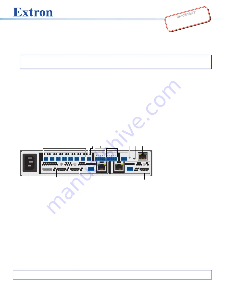
Figure 1 shows the IN1804 DI-DO model as an example, because it contains all input and
output connector types available on the IN1804 series.
•
IN1804 standard
—
Inputs:
Three HDMI and one DisplayPort.
Outputs:
Two HDMI.
•
IN1804 DI
—
Inputs:
Two HDMI, one DisplayPort, and one RJ-45 twisted pair (with IR
pass-through).
Outputs:
Two HDMI.
•
IN1804 DO
—
Inputs:
Three HDMI and one DisplayPort.
Outputs:
One HDMI and one
RJ-45 twisted pair (with IR pass-through).
•
IN1804 DI-DO
—
Inputs:
Two HDMI, one DisplayPort, and one RJ-45 twisted pair
(with IR pass-through).
Outputs:
Two HDMI and one RJ-45 twisted pair (with IR
pass-through).
2
1
1
100-240V ~ 1.3A MAX
50-60 Hz
L
IN R
L OUT R
Tx Rx G
C T
2
C T
3
C T
4
C T
5
C T
6
C T
7
C T
G V+
RS-232
RESET
LA
N
3
4
1B
HDMI/CEC
OUTPUT
S
REMOTE
AUDI
O
CONT
AC
T
/T
AL
LY
INPUTS
Tx Rx G
IR
1A
OVER TP
Tx Rx G
IR
OVER TP
SIG
OUT
LINK
SIG
IN
LINK
A
D
C
E
F
I
K J
M
Q
L
N
B
O
P
G
H
Figure 1.
Rear Panel Connectors, IN1804 DI-DO
Mounting and Cabling
Step 1 — Mount the device
a.
Turn off or disconnect all equipment power.
b.
Place the scaler on top of a flat surface using the provided rubber feet, mount it under a table using an optional kit for under
desk mounting, or attach it to a rack shelf using an optional rack shelf-mounting kit (kits are available at
).
Step 2 — Connect inputs
Connect one or more of the following input sources as appropriate:
•
Connect a DP source to the input 1 DisplayPort connector (see figure 1,
B
).
•
Connect HDMI or DVI (with an appropriate adapter) video sources to HDMI input 2, input 3, and input 4 (available on IN1804
standard and DO models only) connectors (
C
). Securing the HDMI cables with provided LockIt brackets is recommended
(see the
IN1804 Series User Guide
for instructions).
•
Connect a balanced or unbalanced audio source to the 5-pole captive screw AUDIO IN connector (
page 3 for more information.
A
AC power connector
B
DisplayPort input connector
C
HDMI input connectors
D
Over TP IR pass-through
connector for input
E
TP RJ-45 input connector
F
TP RJ-45 output connector
G
Over TP IR pass-through
connector for output
H
HDMI output connector
I
LAN connector
J
Reset button
K
Reset LED
L
Remote RS-232 connector
M
Analog audio output
N
Analog audio input
O
+V port (for tally voltage output)
P
Ground pin (for contact ports)
Q
Contact/tally connectors
For information on safety guidelines, regulatory compliances, EMI/EMF compatibility, accessibility, and related topics, see the
Extron Safety and Regulatory Compliance Guide
on the Extron website.


