Extron electronics Hideaway HSA 400 US/domestic User Manual Download Page 6

HSA 400/402 Series • Introduction

HSA 400/402 Series • Introduction

Introduction

About the Hideaway

®

 Surface Access Products

The patented Extron Hideaway HSA 400 and HSA 402 are

furniture-mounted, architectural solutions for inconspicuous

computer video interface connector access and control.
The HSA 400 provides space for two double-space

(double-height) or four single-space Extron Architectural

Adapter Plates (AAPs), a standard grounded AC receptacle, and

two RJ-45 (Category 5/6) (CAT 5/6) connectors (figure 1-1).  The

HSA is available in a US version, with a US power receptacle,

and an international version.  Several different types of power

receptacles are available for the international version, including

Universal,


UK, French, Israeli, Australian, Indian, European,

and Swiss receptacles.

The Universal AC outlet is fully compatible with
Europlug, British, Indian, Danish, and Italian plug
types. See the universal AC outlet guide on the Extron
Web site, 

www.extron.com

, for compatibility details on

all plug types.

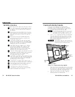
Figure 1-1 — HSA 400 hideaway enclosure

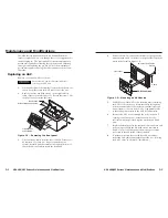
The HSA 402 provides the same AAP space, but with two AC

receptacles and four RJ-45 connectors.  The AC receptacles and

RJ-45 connectors are arranged symmetrically on opposite sides

of the AAP opening (figure 1-2).
In both models, cabling inside the enclosure runs the AC power

line(s) and RJ-45 signal lines from the HSA panel connectors to

connectors on the bottom of the enclosure.
With an optional conversion kit, one or more of the RJ-45 (data)

lines can be converted to an RJ-11 (telephone) line.

1-2

The installed enclosures fit nearly flush within a table or podium

top, storing the AAPs and connectors out of the way and out of

sight.  To access the AAPs and connectors, the user presses

down on the top of the enclosure, releasing a mechanical latch.

A gas lift slowly tips the AAPs and connectors into view.

Figure 1-2 — HSA 402 hideaway enclosure

The functionality of the HSA enclosures can be optimized with

one or two RGB 580

xi

 AAPs connected and routing video and

audio signals to one or two RGB 580

xi

 Remote Interfaces

(figure 1-3, on the next page).

Features

UL/c-UL listing / CSA certification

Easy access to connectors and controls

Durable mechanical movement and latching mechanism

A variety of surface finishes

A variety of RJ-45 connector bezel colors included:  black,
red, blue, orange, gray, white, ivory, yellow, and green

The space behind the AAP panel is limited.  The on-line
Connectivity Configurator, available at

www.extron.com

, offers guidance as to the fit of AAPs

into this space.

Compact size

Easy installation of two double-space Extron AAPs

RJ-45 (CAT 5/6) network, data, or communications
connections (teminated in accordance with the

TIA/EIA T 568 A

 standard)

Grounded AC receptacle(s)

1-3

Summary of Contents for Hideaway HSA 400 US/domestic

Page 1: ...800 3987 6673 Inside Europe Only 31 33 453 4040 31 33 453 4050 FAX Extron Asia 800 7339 8766 Inside Asia Only 65 6383 4400 65 6383 4664 FAX Extron Japan 81 3 3511 7655 81 3 3511 7656 FAX Extron China...

Page 2: ...sollten Sie alle Netzkabel aus der R ckseite des Ger tes aus der externen Stomversorgung falls dies m glich ist oder aus der Wandsteckdose ziehen Schutz des Netzkabels Netzkabel sollten stets so verl...

Page 3: ...s s s s s s s s s s s...

Page 4: ...ntenance and Modifications 3 1 Replacing an AAP 3 2 Replacing the Bezels 3 4 Removing and Replacing the Enclosure 3 5 Replacing the Gas Lift 3 8 Adjusting the Top Surface Level 3 10 Appendix A Referen...

Page 5: ...Contents cont d HSA 400 402 Series Surface Access Products 1 Chapter One Introduction About the Hideaway Surface Access Products Features 68 604 01 Rev G 06 09 All trademarks mentioned in this manual...

Page 6: ...abling inside the enclosure runs the AC power line s and RJ 45 signal lines from the HSA panel connectors to connectors on the bottom of the enclosure With an optional conversion kit one or more of th...

Page 7: ...tron HSA 402 Extron RGB 580xi Mounted under a table or podium Mounted through a table or podium SOG SERR DDSP V SYNC WIDTH NEG SYNC COMP SYNC INPUT S RGB 580 xi ANAL OG AUDIO CONT ROL VIDEO OUTPU T LE...

Page 8: ...enclosure as follows 1 If you have an unprepared mounting template prepare the template See Preparing the Routing Template on the next page 2 If desired install the optional RJ 45 to RJ 11 conversion...

Page 9: ...he wooden strips on the routing template contact the furniture Failure to do so may mar the furniture 2 Place the mounting template assembly on the table centered on the mounting location Angle the te...

Page 10: ...le at www extron com offers guidance as to the fit of AAPs into this space The various Extron single and double space AAP devices including the various RGB 580xi AAPs can be mounted to the HSA See app...

Page 11: ...0 12 5 50 60 Hz 0 5A COMPU TE R INPU T SE LE CT AUDIO Figure 2 5 Mounting an AAP device to an HSA 400 US front panel 4 Replace the front panel in the surface mount enclosure and secure it in place wit...

Page 12: ...com for compatibility details on all plug types 3 Cable access holes Cabling the RJ 45 connectors Plug one end of a twisted pair TP cable into each of these RJ 45 female connectors on the underside o...

Page 13: ...t of the top panel Figure 2 9 shows the cables routed to the side which proved effective in tests at Extron 3 Secure the AAP cables to the tie down holes with tie wraps in the clamshell and the enclos...

Page 14: ...lation cont d HSA 400 402 Series Surface Access Products 3 Chapter Three Maintenance and Modifications Replacing an AAP Replacing the Bezels Removing and Replacing the Enclosure Replacing the Gas Lift...

Page 15: ...ar of the AAPs that are to be replaced If a cable is no longer required in your system carefully pull the cable out through the bottom of the surface mount enclosure and the clamshell 4 Remove the AAP...

Page 16: ...in place with the hex head screws that were removed in step 1 Removing and Replacing the Enclosure The procedure for replacing the gas lift requires removing the HSA 400 or HSA 402 from the table Adj...

Page 17: ...Washer IEC Power Cord 4 RJ 45 Connectors HS A 402 Clamshell Figure 3 5 Removing the HSA 402 from the table 3 7 3 6 9 Perform the desired maintenance procedure 10 If the surface is not level adjust the...

Page 18: ...e center of the enclosure releasing the mounting plate from the enclosure figure 3 6 4 Turn the gas lift mounting plate counterclockwise until the pivot nut on the plate comes free from the shaft of t...

Page 19: ...nclosure steps 1 through 8 2 If necessary close and latch the top panel 3 Slightly loosen the two latch locking screws figure 3 8 on the underside of the surface mount enclosure These screws lock the...

Page 20: ...D 20 61 0 083 cm W x 15 05 0 083 cm D Clamshell figure A 1 A 5 25 13 3 cm B 7 75 19 7 cm C 7 75 19 7 cm HSA 402 US domestic Top plate outer rim 10 844 W x 6 425 D 27 54 cm W x 16 32 cm D Top plate til...

Page 21: ...rted colors 70 201 01 1 4 20 1 1 2 2 full thread bolts M6 x 25 mm 40 mm 50 mm 65 mm full thread bolts Routing Templates Template Part number HSA 400 US domestic routing template 70 189 01 HSA 400 Inte...

Page 22: ...ll help you properly prepare the mounting surface The cutout templates are not to scale and are for reference only The surface cut out area dimensions on all templates are C and D and marked in bold t...

Page 23: ...m D 5 925 0 0325 15 05 0 083 cm SURFACE CUT OUT AREA 9 613 0 0325 24 42 0 083 cm x 5 925 0 0325 15 05 0 083 cm Figure A 6 HSA 400 International cut out template A 8 Cut surface material out along this...

Page 24: ...0 083 cm x 5 925 0 0325 15 05 0 083 cm User Access Connectors and AAP Openings Cut surface material out along this line Tilting Plate Top Panel Cut Out Template for Extron s HSA 402 TEMPLATE IS NOT F...

Page 25: ...sonal injury CAUTION The flanged edges of the top of the surface enclosure are bevelled to an ultra fine thickness of less than 0 04 4 100 approximately 1 mm These edges are soft and can be easily nic...

Page 26: ...ct the flanged edges of the top of the surface enclosure figure B 4 Figure B 4 Installing protective strips 7 Release tilt up the top panel 8 Insert the HSA and the clamshell into one of the foam shel...

Page 27: ...he remaining foam shell figure B 6 Firmly push the foam shells together as far as they will go to completely suspend the HSA and clamshell The sides of the clamshell protrude through slots in the foam...

Page 28: ...ra foam that was included in the return kit Insert the foam vertically in the carton s corners on one side of the carton and horizontally on the other side of the carton figure B 8 Vertical Foams Hori...

Reviews: