


4
DTP2 R 212 Series • Setup Guide (Continued)
(see
)— Press and hold to enable toggling between normal and auto switch modes.
— Toggles between auto switch and manual mode (see “Selecting the switch mode,” below).
(6) —
Signal LEDs
(3) — Lights when a signal is detected on the applicable input or the output.
HDCP LEDs
(3) — Lights when the HDMI signal is encrypted on the applicable input or the output.
Power
When AC power is applied, the switcher performs a self-test that blinks the front panel LEDs. An error-free power up self-test leaves the
Auto Switch and Input LEDs on or off in the same configuration as they were when power was last removed.
Plug in all system components and turn on the input devices, the connected DTP transmitter, and the output device. Set the input devices
to output video using the operating instructions for those devices. Select an input. The image should appear on the screen.
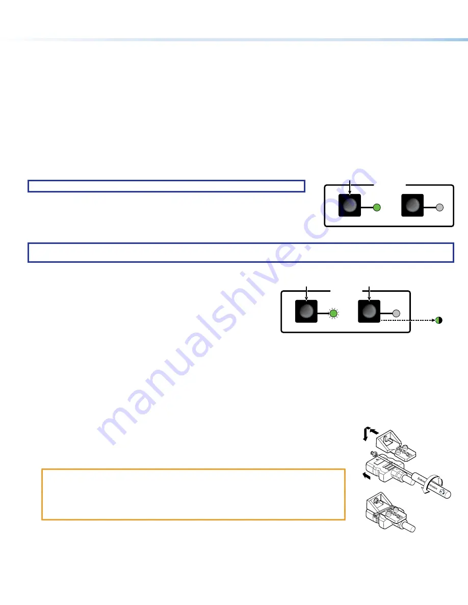
Switching inputs
1
INPUTS
MODE
NORM/AUTO
Press the button.
The LED lights green.
NOTE:
The switcher must be in normal (manual) mode.
Select the desired input by pressing the associated input button.
Observe that the LED for the selected input lights.
Selecting the switch mode
NOTE:
In the auto-input switching mode that is available from the front panel, the switcher automatically selects the input with a sync
signal present, with input 2 taking priority if both have sync.
Turn auto-input switching mode on and off as follows:
AUTO
SWITCH
1
INPUTS
MODE
NORM/AUTO
Press and
HOLD
the button.
Release
the button.
Auto Switch
lights (auto)
or goes out
(normal).
Press and release
the button.
3
seconds
1
3
2
5
4
1.
Press and hold the
Mode
(Input 1) button for approximately 3 seconds (
1
)
until the Input 1 LED blinks (
2
).
2.
Release the button (
3
).
3.
As necessary press and release the
Norm
/
Auto
(Input 2) button (
4
).
The Input 1 LED goes off. The Auto Switch LED (
5
) indicates as follows.
Auto mode
— Auto Switch lights.
Normal mode
— Auto Switch is unlit.
Making Connections
HDMI Connectors
1.
Plug the HDMI cable into the panel connection (see
1
, at right).
3
3
3
1
1
5
5
4
4
2
2
2.
Loosen the HDMI connection mounting screw from the panel enough to allow the LockIt lacing
bracket to be placed over it. The screw does not have to be removed.
3.
Place the LockIt lacing bracket on the screw and against the HDMI connector, then tighten the
screw to secure the bracket.
ATTENTION
:
•
Do not overtighten the HDMI connector mounting screw. The shield it fastens to is very
thin and can easily be stripped.
•
Ne serrez pas trop la vis de montage du connecteur HDMI. Le blindage auquel elle est
attachée est très fin et peut facilement être dénudé.
4.
Loosely place the included tie wrap around the HDMI connector and the LockIt lacing bracket as
shown.
5.
While holding the connector securely against the lacing bracket, use pliers to tighten the tie wrap, then remove any excess length.


