


2-5
Annotator • Installation
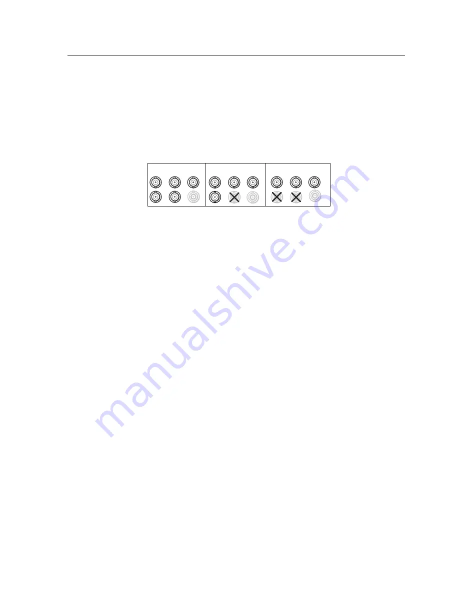
RGBHV
H
/
HV
R
/R-Y
V
G
/Y
B
/B-Y
R
/R-Y
V
G
/Y
RGBS/ RGBcvS video
H/
HV
B
/B-Y
R
/
R-Y
G
/
Y
B/
B-Y
RGsB/
Component Video
(Y, R-Y, B-Y)
H/
HV
V
S
S
S
g
Optional input board (HD-SDI/SDI
with BNC’s shown) connector (input 7)
—
Connect an appropriate input to the optional board connector.
Output, user interface, and control connections
h
RGB/YUV-HD BNC connectors
—
Connect a display to these for RGB or HD
component video output.
i
RGB/YUV-HD 15-pin VGA connector
—
Connect a display to this for RGB or
HD component video output.
j
Optional output card (scan converter with BNC connectors shown)
—
Connect a display to this for composite, S-video, or component video output.
k
MTP output
—
Connect a mini twisted pair receiver to this port
l
PS/2 mouse port
—
Connect a PS/2 mouse to this port for annotation use.
m
Keyboard port —
Connect a Microsoft
®
compatible keyboard to this port for
annotation use.
n
USB A ports —
Connect up to twenty touch panel devices (using USB hubs),
or a USB mouse and keyboard to these ports.
o
LAN Ethernet port
—
Connect the Annotator to an Ethernet LAN or WAN
via this RJ-45 connector. Ethernet control allows the operator to control the
processor from a remote location. When connected to an Ethernet LAN or
WAN, the device can be accessed and operated from a computer running a
standard Internet browser. The Link LED lights green when the Annotator
is connected to an Ethernet LAN, and the Act LED flickers amber, indicating
data transmission as the devices communicate.
C
Do not connect the MTP cable to the LAN port, or connect the LAN cable
to the MTP port.
N
Do not use standard telephone cables, as they do not support Ethernet or Fast
for correct cabling.
Do not stretch or bend cables. Transmission errors can occur.
N
See chapter 5, “SIS Programmer’s Guide”
, for definitions of the SIS commands
and
chapter 6, “Annotator Software”
to install and use the control software.
p
Remote (RS-232) 9-pin ports
— These connectors provides for two-way
RS-232 communication. Connect a host computer or control system via a
9-pin D connector
p
for serial RS-232 or RS-422 control.
For touch panels,
using a NULL RS-232 cable only
, connect the touchscreen
to the Annotator via either of the RS-232 comm ports. RS-232 driver
configuration is necessary and can be done using the Signal Processing
Products Control Program. Within the SPPCP program click
Help
>
Contents
for configuration instructions.
The default protocol is 9600 baud, 1 stop bit, no parity, and no flow control.
q
Ethernet connection indicators
— The LEDs marked “Link” and “Act”
indicate the status of the Ethernet connection.


