background image

53

ExtremeSwitching SLX 9140 Hardware Installation Guide


9036857-00 Rev AA

Inserting a new DC power supply

a.

Press the release lever on the filler panel.

b.

Remove the filler panel.

3.

Before opening the package that contains the power supply, touch the bag to the switch casing to discharge any potential static
electricity. Extreme recommends using an ESD wrist strap during installation.

4.

Remove the power supply from the anti-static shielded bag.

5.

Holding the power supply level, guide it into the carrier rails on each side and gently push it all the way into the slot, ensuring that
it firmly engages with the connector and the release lever clicks into its locked position.

When the SLX 9140 switch is powered on, the LEDs on the power supply rear panel should light up green to confirm that the power 
supply is correctly installed and supplying power.

Inserting a new DC power supply

NOTE

This equipment installation must meet NEC/CEC code requirements. Consult local authorities for regulations.

Use the following steps to install a DC power supply in the SLX 9140 switch.

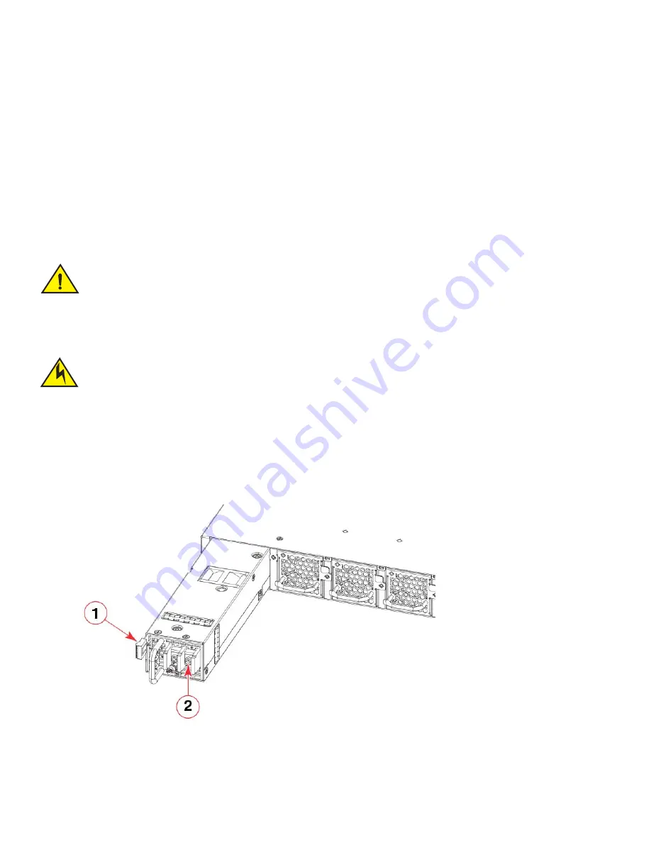
FIGURE 34

Installing a DC power supply unit

CAUTION

If you do not install a power supply in a slot, you must keep the slot filler panel in place. If you run the device with an uncovered 
slot, the system will overheat.

CAUTION

All devices with DC power supplies are intended for installation in restricted access areas only. A restricted access area is 
where access can be gained only by service personnel through the use of a special tool, lock and key, or other means of 
security, and is controlled by the authority responsible for the location.

1

Release lever

2

DC power supply terminals

Summary of Contents for ExtremeSwitching SLX 9140

Page 1: ...9036857 00 Rev AA October 20 2020 ExtremeSwitching SLX 9140 Hardware Installation Guide HARDWARE INSTALLATION GUIDE ...

Page 2: ...ered trademarks of Extreme Networks Inc in the United States and or other countries All other names are the property of their respective owners For additional information on Extreme Networks Trademarks please see www extremenetworks com company legal trademarks Specifications and product availability are subject to change without notice ...

Page 3: ... side view of the SLX 9140 switch 4 Device management options 4 Preparing for Installation Safety precautions 5 General precautions 5 ESD precautions 6 Power precautions 6 Lifting precautions 7 Laser precautions 7 Facility requirements 8 Electrical considerations 8 Environmental considerations 8 Location considerations 8 Rack considerations 9 Recommendations for cable management 9 Quick installati...

Page 4: ...e fiber optic connectors 39 Managing cables 40 Installing a fiber optic transceiver 40 Replacing a fiber optic transceiver 41 Removing a fiber optic transceiver 41 Connecting network devices 42 Connectors 42 Connecting a network device to a copper port 42 Connecting a network device to a fiber port 42 Monitoring the Device LED activity interpretation 45 SLX 9140 port side LEDs 45 SLX 9140 nonport ...

Page 5: ...nfiguration 63 Power consumption maximum configuration 63 Data port specifications Ethernet 63 Serial port specifications pinout mini USB 64 Serial port specifications protocol 64 Memory specifications 64 Regulatory compliance EMC 64 Regulatory compliance safety 65 Regulatory compliance environmental 65 Regulatory Statements USA FCC CFR 47 Part 15 Warning 67 Industry Canada statement 67 Europe and...

Page 6: ...vi ExtremeSwitching SLX 9140 Hardware Installation Guide 9036857 00 Rev AA ...

Page 7: ...ATTENTION An Attention statement indicates a stronger note for example to alert you when traffic might be interrupted or the device might reboot Text formatting conventions Text formatting conventions such as boldface italic or Courier font may be used to highlight specific words or phrases CAUTION A Caution statement alerts you to situations that can be potentially hazardous to you or cause damag...

Page 8: ...two ways Use our short online feedback form at http www extremenetworks com documentation feedback pdf Email us at internalinfodev extremenetworks com Provide the publication title part number and as much detail as possible including the topic heading and page number if applicable as well as your suggestions for improvement Identifies document titles Courier font Identifies CLI output Identifies c...

Page 9: ...edgebase or create a help case if you need more guidance The Hub A forum for Extreme customers to connect with one another get questions answered share ideas and feedback and get problems solved This community is monitored by Extreme Networks employees but is not intended to replace specific guidance from GTAC Support Portal Manage cases downloads service contracts product licensing and training a...

Page 10: ...x ExtremeSwitching SLX 9140 Hardware Installation Guide 9036857 00 Rev AA Contacting Extreme Technical Support ...

Page 11: ...onport side exhaust airflow SLX OS 17s 1 00 Yes XBR ACPWR 650 R 650W AC power supply with nonport side intake airflow SLX OS 17s 1 00 Yes XBR DCPWR 650 F 650W DC power supply with nonport side exhaust airflow SLX OS 17s 1 00 Yes XBR DCPWR 650 R 650W DC power supply with nonport side intake airflow SLX OS 17s 1 00 Yes TABLE 2 Fan assemblies Part number Description Introduced OS Currently supported ...

Page 12: ...2 ExtremeSwitching SLX 9140 Hardware Installation Guide 9036857 00 Rev AA Supported hardware and software ...

Page 13: ... GbE transceivers QSFP28 ports supporting 100 GbE and 40 GbE transceivers including support for 2x50 GbE 4x25 GbE and 4x10 GbE breakout transceivers The QSFP28 ports can be configured in 4x25 GbE breakout mode for a total of 72x25 GbE ports Multi speed configuration support for some qualified passive cables Dual redundant hot swappable power supplies available with intake or exhaust airflow 650 W ...

Page 14: ...OST each time it is turned on You can manage the switch using any of the management options listed in the following table 1 10 100 1000Base T RJ 45 management port 4 USB port for flash drive 2 SFP28 ports 1 48 5 Mini USB console port 3 QSFP28 ports 49 54 6 System LEDs 1 Power supply unit 1 3 Power supply unit 2 2 Fans 1 6 TABLE 1 Management options for the switch Management tool Out of band suppor...

Page 15: ...ions DANGER Be careful not to accidently insert your fingers into the fan tray while removing it from the chassis The fan may still be spinning at a high speed CAUTION Changes or modifications made to this device that are not expressly approved by the party responsible for compliance could void the user s authority to operate the equipment CAUTION Disassembling any part of the power supply and fan...

Page 16: ...osion if battery is replaced by an incorrect type Dispose of used batteries according to the manufacturer s instructions DANGER For safety reasons the ESD wrist strap should contain a series 1 megohm resistor CAUTION Static electricity can damage the chassis and other electronic devices To avoid damage keep static sensitive devices in their static protective packages until you are ready to install...

Page 17: ...ermine the possibility of overloading the supply circuits add the ampere amp ratings of all devices installed on the same circuit as the device Compare this total with the rating limit for the circuit The maximum ampere ratings are usually printed on the devices near the input power connectors DANGER Use safe lifting practices when moving the product DANGER Mount the devices you install in a rack ...

Page 18: ... configuration The ambient air temperature does not exceed 50 C 122 F while the switch is operating with front to back airflow or 45 C 113 F while the switch is operating with back to front airflow Location considerations Before installing the device plan its location and orientation relative to other devices and equipment Devices can be mounted in a standard 19 inch equipment rack The site should...

Page 19: ...s The following list provides some recommendations for cable management NOTE You should not use tie wraps with fiber optic cables because they are easily overtightened and can damage the optical fibers Velcro like wraps are recommended Plan for the rack space required for cable management before installing the device Leave at least 1 m 3 28 ft of slack for each port cable This provides room to rem...

Page 20: ...ess security No default password is assigned to the CLI Extreme SLX OS Command Reference for the SLX 9140 and 9240 switches 6 Before attaching equipment to the device you must configure an interface IP address to the subnet on which the device will be located Initial IP address configuration is performed using the CLI with a direct serial connection Extreme SLX OS Command Reference for the SLX 914...

Page 21: ... 46 cm and 79 cm 18 to 31 in deep In a two post Telco rack using the Universal Two Post Rack Kit XBR R000294 The two post rack kit supports various mounting positions In a four post EIA rack using the Universal Four Post Rack Kit XBR R000296 The rack kit can be used to install devices in EIA racks that are between L 13 7 to 81 28 cm deep L 5 0 to 32 0 in where L is the chassis depth Precautions sp...

Page 22: ... R000297 on page 12 for the installation procedure To mount the product into a two post rack you can order the two post rack kit with the part number XBR R000294 For the procedure to install this kit refer to Installing the Universal Two Post Rack Kit XBR R000294 on page 16 To mount the product into a four post rack you can also order the four post rack kit with the part number XBR R000296 For the...

Page 23: ...d in the kit Flush front mounting Complete the following tasks to install the device in a four post rack 1 Attaching the front brackets on page 14 2 Installing the device in the rack on page 14 3 Attaching the rear brackets to the rack posts on page 15 1 Front brackets 2 3 Screw 10 32 x 5 8 in panhead Phillips 8 2 Rear brackets 2 4 Retainer nut 10 32 8 CAUTION Use the screws specified in the proce...

Page 24: ...the device FIGURE 4 Attaching the front brackets Installing the device in the rack Complete the following steps to install the device in the rack 1 Position the device in the rack as shown in Figure 5 providing temporary support under the device until the rail kit is secured to the rack 2 Attach the right front bracket to the right front rack post using two 10 32 x 5 8 in panhead screws and two re...

Page 25: ...acket into the left front bracket 2 Adjust the rear brackets to the rack depth 3 Attach the right rear bracket to the right rear rack post using two 10 32 x 5 8 in panhead screws and two retainer nuts as shown in Figure 6 Use the upper and lower holes in the bracket 4 Attach the left rear bracket to the left rear rack post using two 10 32 x 5 8 in panhead screws and two retainer nuts Use the upper...

Page 26: ...R000294 There are two ways you can mount the device in a four post rack With the port side flush with the posts With the switch mid mounted on the posts NOTE Hardware devices illustrated in these procedures are only for reference and may not depict the device you are installing into the rack Time and items required Allow 15 to 30 minutes to complete the installation The following items are require...

Page 27: ...asks to install the device in a two post rack 1 Attaching the front brackets on page 18 2 Attaching the front brackets to the rack posts on page 18 3 Attaching the rear brackets to the rack posts on page 19 1 Front brackets 2 5 Screw 8 32 x 5 16 in flathead Phillips 16 2 Rear brackets 5 6 inch post 2 6 Screw 6 32 x 1 4 in panhead Phillips 8 3 Rear brackets 3 5 inch post 2 7 Screw 10 32 x 5 8 in pa...

Page 28: ...the switch 4 Repeat step 1 and step 2 to attach the left front bracket to the left side of the switch 5 Tighten all 8 32 x 5 16 in screws to a torque of 15 in lb 17 cm kg FIGURE 8 Attaching the front brackets Attaching the front brackets to the rack posts Complete the following steps to install the switch in the rack 1 Position the switch in the rack Figure 9 providing temporary support under the ...

Page 29: ...e inches wide use the brackets marked 3 5 INCH If your posts are five to six inches wide use the brackets marked 5 6 INCH 2 Position the right rear bracket in the right rear of the switch as shown in Figure 10 3 Attach the brackets to the right rack upright using two 10 32 x 5 8 in screws and two retainer nuts Use the top and bottom holes in the bracket 4 Repeat step 2 and step 3 to attach the lef...

Page 30: ...ear of the switch and using four 8 32 x 5 16 in panhead screws attach the bracket to the switch as shown in Figure 11 Be sure to insert the screws through the upper and lower slots in the bracket 2 Align the left rear bracket to the left rear of the switch and using four 8 32 x 5 16 in panhead screws attach the bracket to the switch Again use the upper and lower slots in the bracket 3 Tighten all ...

Page 31: ...24 Attaching the front brackets Complete the following steps to attach the front brackets to the switch 1 Use a 2 Phillips screwdriver to remove the 12 pre installed keyhole fasteners from both sides of the switch 2 Position the right front bracket with the flat side against the right side of the switch as shown in Figure 12 3 Insert four 8 32 x 5 16 in flathead screws through the top and bottom h...

Page 32: ...e rack Figure 13 providing temporary support under the switch until the rack kit is fully secured to the rack 2 Attach the right front bracket to the right rack upright using two 10 32 x 5 8 in screws and two retainer nuts as shown in Figure 13 3 Attach the left front bracket to the left rack upright using two 10 32 x 5 8 in screws and two retainer nuts 4 Tighten all the 10 32 x 5 8 in screws to a...

Page 33: ...5 INCH If your posts are five to six inches wide use the brackets marked 5 6 INCH 2 Position the right rear bracket in the right rear of the switch as shown in Figure 14 Whether you are using the 3 5 inch or 5 6 inch bracket the rear end of the bracket will be flush with the back of the switch 3 Attach the brackets to the right rack upright using two 10 32 x 5 8 in screws and two retainer nuts 4 R...

Page 34: ...ear of the switch and using four 8 32 x 5 16 in panhead screws attach the bracket to the switch as shown in Figure 15 Be sure to insert the screws through the upper and lower slots in the bracket 2 Align the left rear bracket to the left rear of the switch and using four 8 32 x 5 16 in panhead screws attach the bracket to the switch Again use the upper and lower slots in the bracket 3 Tighten all ...

Page 35: ...e front posts With the nonport side flush with the rear posts in a recessed position A recessed position allows a more gradual bend in the fiber optic cables connected to the switch and less interference in the aisle at the front of the rack NOTE Hardware devices illustrated in these procedures are only for reference and may not depict the device you are installing into the rack Installation requi...

Page 36: ...ing parts are provided with the Universal Four Post Rack Kit XBR R000296 FIGURE 16 Rack kit parts Ensure that the items listed and illustrated in Figure 16 are included in the kit Note that not all parts may be used with certain installations depending on the device type 1 Front brackets 2 6 Screw 8 32 x 5 16 in panhead Phillips 8 2 Extension brackets medium 2 7 Screw 8 32 x 5 16 in flathead Phill...

Page 37: ...Phillips screwdriver to remove the 12 pre installed keyhole fasteners from both sides of the switch 2 Position the right front bracket with the flat side against the right side of the device at the front of the device as shown in Figure 17 3 Insert four 8 32 x 5 16 in flathead screws through the vertically aligned holes in the bracket and then into the holes on the side of the device Use the upper...

Page 38: ...rack 1 Select the proper length extension bracket for your rack depth 2 Position the right extension bracket along the side of the device as shown in Figure 18 3 Insert four 8 32 x 5 16 in flathead screws through the vertically aligned holes in the extension bracket and then into the holes on the side of the device Use the upper and lower screw holes leaving the center holes empty 4 Repeat step 2 ...

Page 39: ...g temporary support under the device until the rail kit is secured to the rack 2 Attach the right front bracket to the right front rack post using two 10 32 x 5 8 in panhead screws and two retainer nuts Use the upper and lower holes in the bracket 3 Attach the left front bracket to the left front rack post using two 10 32 x 5 8 in panhead screws and two retainer nuts Use the upper and lower holes ...

Page 40: ...h rear bracket for your rack depth 2 Slide the right rear bracket onto the right extension and attach to the extension by inserting four 6 32 x 1 4 in panhead screws through the bracket holes If possible leave at least one empty vertical pair of holes between the screws for better support 3 Repeat step 2 to attach the left rear bracket to the left extension 4 Adjust the brackets to the rack depth ...

Page 41: ...s in the bracket 3 Tighten all the 10 32 x 5 8 in screws to a torque of 25 in lb 29 cm kg FIGURE 21 Attaching the rear brackets to the rack posts Flush rear recessed mounting The flush rear recessed mounting is similar to the flush front mounting except that the brackets are reversed on the device Complete the following tasks to install the device in a four post rack 1 Attaching the front brackets...

Page 42: ...the bracket and then into the holes on the side of the device Use the upper and lower screw holes leaving the center holes empty 4 Repeat step 1 and step 2 to attach the left front bracket to the left rear side of the device 5 Tighten all the 8 32 x 5 16 in screws to a torque of 15 in lb 17 cm kg FIGURE 22 Attaching the front brackets to the rear of the device Attaching the extensions to the front...

Page 43: ...he rack as shown in Figure 24 providing temporary support under the device until the rail kit is secured to the rack 2 Attach the right front bracket to the right rear rack post using two 10 32 x 5 8 in panhead screws and two retainer nuts Use the upper and lower holes in the bracket 3 Attach the left front bracket to the left rear rack post using two 10 32 x 5 8 in panhead screws and two retainer...

Page 44: ...of your rack 1 Select the proper length rear bracket for your rack depth 2 Slide the right rear bracket onto the right extension as shown in Figure 25 The short rear brackets are shown Use the first and third vertical pairs of holes for the screws Refer to Figure 26 for the positioning of the short or long brackets and screws 3 Attach the brackets using four 6 32 x 1 4 in screws 4 Repeat step 2 an...

Page 45: ...rear brackets to the front rack posts 1 Attach the right rear bracket to the right front rack post using two 10 32 x 5 8 in screws and two retainer nuts as shown in Figure 27 Use the upper and lower holes in the bracket 2 Attach the left rear bracket to the left front rack post using two 10 32 x 5 8 in screws and two retainer nuts Use the upper and lower holes in the bracket 3 Tighten all the 10 3...

Page 46: ...0 Hardware Installation Guide 9036857 00 Rev AA Installing the Universal Four Post Rack Kit XBR R000296 FIGURE 27 Attaching the rear brackets to the front rack posts 1 Screws 10 32 x 5 8 in panhead Phillips 2 Retainer nuts 10 32 ...

Page 47: ...fy that the power and status LEDs are green The power supply LEDs display amber until power on self test POST is complete and then change to green The switch usually requires several minutes to boot and complete POST NOTE To turn the system off simply unplug the power cables For more information about how to interpret LEDs and run diagnostics tests refer to Diagnostic tests and monitoring on page ...

Page 48: ...vironment Baud 9600 bps Data bits 8 Parity None Stop bits 1 Flow control None In a UNIX environment using TIP enter the following string at the prompt tip dev ttyb 9600 If ttyb is already in use use ttya instead and enter the following string at the prompt tip dev ttya 9600 Establishing an Ethernet connection The Gigabit Ethernet management port RJ 45 on the SLX 9140 switch front panel provides an...

Page 49: ...the optic launch power To clean the fiber cable connectors Extreme recommends using a fiber optic reel type cleaner When not using a fiber optic transceiver connector make sure to keep the protective covering in place DANGER All fiber optic interfaces use Class 1 lasers DANGER Laser radiation Do not view directly with optical instruments Class 1M laser products DANGER Use only optical transceivers...

Page 50: ...be provided if there is an issue with a third party transceiver NOTE Extreme branded removable media devices are recommended for proper operation of the device You can install a new transceiver in a slot while the device is powered on and running By default a port automatically detects the transceiver media and its speed and then configures the port accordingly For ports not configured in breakout...

Page 51: ...close the bail Transceivers are keyed to prevent incorrect insertion NOTE Each fiber optic transceiver has a 10 pad gold plated edge connector on the bottom The correct position to insert a fiber optic transceiver in the upper row of ports is with the gold plated edge down The correct position to insert a fiber optic transceiver in the lower row of ports is with the gold plated edge up FIGURE 28 I...

Page 52: ... Extreme devices Connectors For port pinouts refer to Serial port specifications pinout mini USB on page 64 Connecting a network device to a copper port For copper connections to another Extreme device or any other devices use straight through or crossover UTP cabling Automatic MDI or MDIX detection All 10 100 1000 Mbps Ethernet copper ports on the devices support automatic Media Dependent Interfa...

Page 53: ...e information refer to Cleaning the fiber optic connectors on page 39 3 Gently insert the cable connector a tab on each connector should face upward into the transceiver connector until the tab locks into place 4 Observe the link and activity LEDs to determine if the network connections are functioning properly For more information about the LED indicators refer to LED activity interpretation on p...

Page 54: ...44 ExtremeSwitching SLX 9140 Hardware Installation Guide 9036857 00 Rev AA Connecting network devices ...

Page 55: ...boot POST or other diagnostic tests This is normal it does not indicate a problem unless the LEDs do not indicate a healthy state after all boot processes and diagnostic tests are complete SLX 9140 port side LEDs The SLX 9140 switch has the following LEDs on the front panel One power single color status LED green One status bicolor status LED green and amber Two management single color LEDs green ...

Page 56: ...s on the SLX 9140 switch rear panel FIGURE 30 SLX 9140 nonport side LEDs 1 Management port link LED 6 QSFP28 port 4x25 10 GbE mode lane 3 link activity LED 2 Management port speed LED 7 QSFP28 port 4x25 10 GbE mode lane 4 link activity LED 3 SFP28 ports 1 48 link activity LEDs 8 Power LED 4 QSFP28 port 100 40 GbE and 2x50 GbE mode link activity LED or 4x25 10 GbE mode lane 1 link activity LED 9 St...

Page 57: ... LED LED state Status of hardware Recommended action Off no light Not cabled No action required Steady green Link is up in 1 GbE mode No action required TABLE 7 1 10 25 GbE SFP28 port LEDs LED state Status of hardware Recommended action Off no light Not cabled No action required Steady green Link is up No action required Blinking green There is traffic and packets are being transmitted or received...

Page 58: ...put LED LED state Status of hardware Recommended action Off no light Power supply is not receiving external power Verify that the power supply power cord is connected to a functioning power source Steady green Power supply is receiving external power No action required Blinking green with power cord connected Power supply has a fault Replace the power supply TABLE 11 Power supply output LED LED st...

Page 59: ...at the SLX 9140 switch operate with two power supplies and five fan assemblies installed If a power supply or fan assembly fails it must be replaced as soon as possible NOTE AC and DC power supplies can be installed and used in the same device The power supplies in the SLX 9140 switch chassis can be removed and replaced without special tools The device can continue operating during the replacement...

Page 60: ...GURE 31 AC power supply FIGURE 32 DC power supply Precautions specific to power supplies 1 Release lever 2 Power supply handle 1 Release lever 2 Power supply handle DANGER Make sure that the power source circuits are properly grounded then use the power cord supplied with the device to connect it to the power source ...

Page 61: ...ds in your country The mark is your assurance that the power cord can be used safely with the device CAUTION Disassembling any part of the power supply and fan assembly voids the warranty and regulatory certifications There are no user serviceable parts inside the power supply and fan assembly CAUTION Ensure that the airflow direction of the power supply unit matches that of the installed fan tray...

Page 62: ...n assemblies All must be either exhaust or intake Inserting a new AC power supply Use the following steps to install an AC power supply in the SLX 9140 switch FIGURE 33 Installing an AC power supply unit 1 If replacing a power supply remove the previously installed power supply from the appropriate slot by pressing the release lever and pulling the power supply handle 2 If installing a new power s...

Page 63: ...he power supply rear panel should light up green to confirm that the power supply is correctly installed and supplying power Inserting a new DC power supply NOTE This equipment installation must meet NEC CEC code requirements Consult local authorities for regulations Use the following steps to install a DC power supply in the SLX 9140 switch FIGURE 34 Installing a DC power supply unit CAUTION If y...

Page 64: ...tential static electricity Extreme recommends using an ESD wrist strap during installation 5 Remove the DC power supply from the anti static shielded bag 6 Remove the DC terminals plastic cover 7 Attach the safety grounding wire to the power supply using the safety ground screw 8 Attach the DC power supply wires to the power supply DC power terminals matching the polarity Refer to Figure 35 FIGURE...

Page 65: ... that there is a good electrical connection to the grounding point on the rack no paint or isolating surface treatment 3 Crimp the included grounding lug to a grounding wire of at least 6 American Wire Gauge AWG The 6 AWG wire and grounding lug should be crimped together using a proper tool 4 Attach the 6 AWG stranded copper wire to the grounding terminal on the SLX 9140 switch using the screws fl...

Page 66: ...0 switch NOTE The terminal for the connection of a grounding conductor is not to be used with an aluminum conductor NOTE To ensure adequate bonding when attaching the ground lug a minimum of 20 in lb 2 76 Nm of torque is required to be applied to the mounting hardware used to attach the ground lug ...

Page 67: ...with 5 fan assemblies If the second power supply and any fan slots are unused you must cover them with filler panels NOTE Extreme recommends that the SLX 9140 switch operates with 2 power supplies and 5 fan assemblies installed If a power supply or fan assembly fails it must be replaced as soon as possible The fan assemblies in the SLX 9140 switch chassis can be removed and replaced without specia...

Page 68: ...fan may still be spinning at a high speed CAUTION Disassembling any part of the power supply and fan assembly voids the warranty and regulatory certifications There are no user serviceable parts inside the power supply and fan assembly CAUTION Ensure that the airflow direction of the power supply unit matches that of the installed fan assembly The power supplies and fan assemblies are clearly labe...

Page 69: ...stalled fan assemblies All must be either exhaust or intake Inserting a new fan assembly Use the following steps to install a fan assembly in the SLX 9140 switch FIGURE 38 Installing a fan assembly 1 If replacing a fan assembly a Using a Phillips screwdriver unscrew the captive screw on the fan assembly b Remove the fan assembly from the chassis by pulling the handle on the fan assembly out and aw...

Page 70: ...y oriented before continuing 5 Holding the fan assembly level guide it into the carrier rails on each side and gently push it all the way into the slot ensuring that it firmly engages with the connector 6 When you are sure the fan assembly has properly engaged the connector tighten the captive screw to secure the fan assembly in the slot NOTE The fans are controlled automatically by the device Whe...

Page 71: ...rnet System component Description Enclosure Chassis mountable on a desktop or in a standard 2 or 4 post rack Power supplies Dual redundant hot swappable power supplies supported with 650 W AC intake or exhaust airflow or 650 W DC intake or exhaust airflow Fans Five 4 1 redundant hot swappable fan assemblies with intake or exhaust airflow A sixth fan assembly can be installed for extended temperatu...

Page 72: ...ional temperature is measured at sea level with at least 4 fan assemblies with maximum power consumption optics modules 5W QSFP28 2W SFP28 fully loaded 5 C to 50 C 23 F to 122 F F2B 5 C to 45 C 23 F to 113 F B2F temporarily to 55 C with 6 fan assemblies 40 C to 70 C 40 F to 158 F Relative humidity 5 to 95 at 50 C 122 F 5 to 95 at 70 C 158 F Altitude 0 to 3 000 m 9 843 ft safety 60 to 4 000 m 13 12...

Page 73: ...R ACPWR 650 R 650 W 100 240V 50 60Hz 12 A Fuses 25A XBR DCPWR 650 F 650 W 48 60V 14 A Fuses 25A XBR DCPWR 650 R 650 W 48 60V 13 3 A Fuses 25A 100 VAC Input Input power 5 200 VAC Input Input power 5 48VDC Minimum number of power supplies Notes 174 W 594 BTU hr 171 W 583 BTU hr 173 W 590 BTU hr 1 x 650 W AC 1 x 650 W DC 1 power supply 184 W 628 BTU hr 181 W 618 BTU hr 183 W 624 BTU hr 1 x 650 W AC 1...

Page 74: ... Canada Class A AS NZ 55032 Australia New Zealand Class A VCCI Japan Class A EN 300 386 CNS 13438 BSMI Taiwan Class A KN 32 South Korea Class A KN 35 South Korea Class A TCVN 7189 TCVN 7317 Vietnam Class A EN 61000 3 2 Pin Signal Description 1 Reserved Not used 2 UART0_RX Debug port data received by SLX 3 UART0_TX Console port data transmitted by SLX 4 Reserved Not used 5 GND Ground Parameter Valu...

Page 75: ...cal and electronic equipment EU RoHS 2012 19 EU Waste electrical and electronic equipment EU WEEE 94 62 EC packaging and packaging waste EU 2006 66 EC batteries and accumulators and waste batteries and accumulators EU battery directive 1907 2006 of the European Parliament and of the Council of 18 December 2006 concerning the Registration Evaluation Authorisation and Restriction of Chemicals EU REA...

Page 76: ...66 ExtremeSwitching SLX 9140 Hardware Installation Guide 9036857 00 Rev AA Regulatory compliance environmental ...

Page 77: ...eration of this equipment in a residential area is likely to cause harmful interference in which case the user will be required to correct the interference at his own expense NOTE Changes or modifications made to this device which are not expressly approved by Extreme could void the user s authority to operate the equipment Industry Canada statement Cet appareil numérique de la classe A est confor...

Page 78: ... environment radio disturbance may arise When such trouble occurs the user may be required to take corrective actions Japan power cord English translation of above statement ATTENTION Never use the power cord packed with your equipment for other products Korea English translation of above statement Class A device Broadcasting Communication Device for Office Use This device obtained EMC registratio...

Page 79: ...tallation Guide 9036857 00 Rev AA China China English translation of above statement This is a Class A product In a domestic environment this product may cause radio interference in which case the user may be required to take adequate measures ...

Page 80: ...857 00 Rev AA BSMI statement Taiwan BSMI statement Taiwan English translation of above statement Warning This is a class A product In a domestic environment this product may cause radio interference in which case the user may be required to take adequate measures ...

Page 81: ...rtie responsable d en évaluer la conformité sont susceptibles d annuler le droit de l utilisateur à utiliser cet équipement PRECAUCIÓN Si se realizan cambios o modificaciones en este dispositivo sin la autorización expresa de la parte responsable del cumplimiento de las normas la licencia del usuario para operar este equipo puede quedar anulada CAUTION Disassembling any part of the power supply an...

Page 82: ...de alimentación y las bandejas del ventilador están etiquetadas claramente con una flecha verde y una E o con una flecha naranja y una I CAUTION To protect the serial port from damage keep the cover on the port when not in use VORSICHT Um den seriellen Anschluss vor Beschädigungen zu schützen sollten Sie die Abdeckung am Anschluss belassen wenn er nicht verwendet wird MISE EN GARDE Mettre le bouch...

Page 83: ...a temperatura ambiente de operación pueda exceder los 50 C 122 F CAUTION Risk of explosion if battery is replaced by an incorrect type Dispose of used batteries according to the manufacturer s instructions VORSICHT Es besteht Explosionsgefahr wenn ein unzulässiger Batterietyp eingesetzt wird Verbrauchte Batterien sind entsprechend den geltenden Vorschriften zu entsorgen MISE EN GARDE Risque d expl...

Page 84: ...on suministros de corriente continua han sido diseñados únicamente para instalación en áreas restringidas Se entiende como área de acceso restringido un lugar al que solo puede acceder personal de servicio mediante el uso de una herramienta especial llave y cerrojo u otro medio de seguridad similar y que esté controlado por la autoridad responsable de esa ubicación CAUTION Static electricity can d...

Page 85: ...é nominale maximum en ampères est généralement imprimée sur chaque dispositif près des connecteurs d entrée d alimentation PRECAUCIÓN Verifique que el instrumento no sobrecargue los circuitos de corriente el cableado y la protección para sobrecargas Para determinar la posibilidad de sobrecarga en los circuitos de suministros añada las capacidades nominales de corriente amp de todos los instrumento...

Page 86: ...istrado con el dispositivo unido a un extremo de modo que el otro extremo se conecte a la toma de tierra El conector se debe engarzar con la herramienta adecuada de forma que se pueda conectar a los dos tornillos de conexión a tierra del compartimento Antes de engarzar el cable de conexión a tierra a la patilla de conexión a tierra proporcionada asegúrese de limpiar y aplicar antioxidante al alamb...

Page 87: ...that the power source circuits are properly grounded then use the power cord supplied with the device to connect it to the power source GEFAHR Stellen Sie sicher dass die Stromkreise ordnungsgemäß geerdet sind Benutzen Sie dann das mit dem Gerät gelieferte Stromkabel um es an die Srromquelle anzuschließen DANGER Vérifiez que les circuits de sources d alimentation sont bien mis à la terre puis util...

Page 88: ... mit dem Gerät gelieferte Kabel nicht passt müssen Sie sicherstellen dass Sie ein Stromkabel mit dem Siegel einer Sicherheitsbehörde verwenden die für die Zertifizierung von Stromkabeln in Ihrem Land zuständig ist Das Siegel ist Ihre Garantie dass das Stromkabel sicher mit Ihrem Gerät verwendet werden kann DANGER Si l installation nécessite un cordon d alimentation autre que celui fourni avec le d...

Page 89: ...R Montieren Sie die Geräte im Gestell so tief wie möglich Platzieren Sie das schwerste Gerät ganz unten während leichtere Geräte je nach Gewicht je schwerer desto tiefer darüber untergebracht werden DANGER Montez les dispositifs que vous installez dans un bâti aussi bas que possible Placez le dispositif le plus lourd en bas et le plus léger en haut en plaçant tous les dispositifs progressivement d...

Page 90: ...0825 erfüllen Optische Produkte die diese Normen nicht erfüllen können Strahlen aussenden die für das menschliche Auge gefährlich sind DANGER Utilisez uniquement des émetteurs récepteurs optiques certifiés par Extreme Networks Inc et conformes aux exigences sur la puissance de rayonnement de catégorie 1 de la FDA définies au sous chapitre 21 CFR I et à les normes IEC 825 et EN60825 Les produits op...

Reviews: