Extreme Networks ExtremeMobility AP410i/e Installation Manual Download Page 22

2 Open the movable sliding part of the DCMTR01 bracket to give the stationary end of the bracket and

the slider T-bar more space.

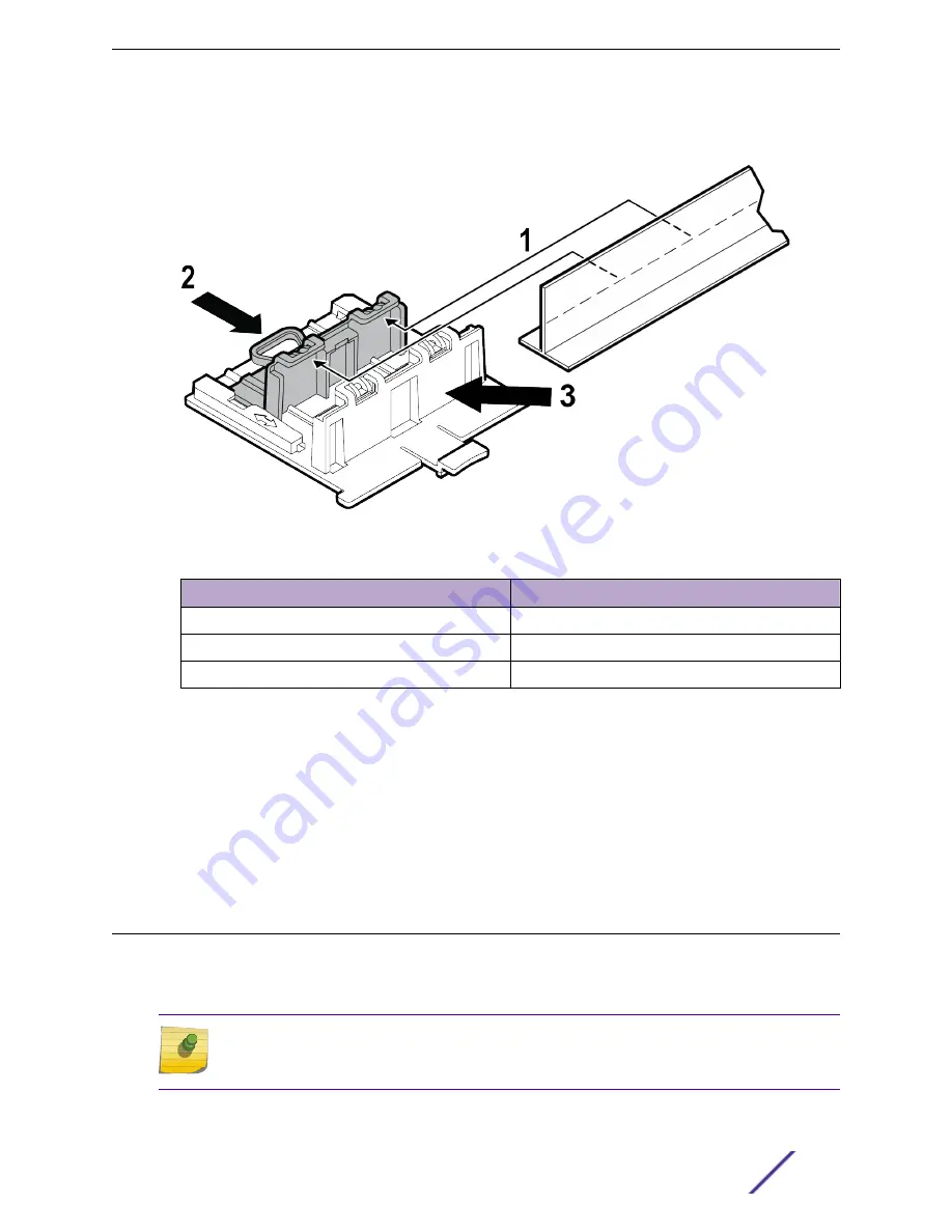
Figure 7: DCMTR01 bracket parts and T-bar

Callout

Description

1

T-bar

2

Movable sliding part of the DCMTR01 bracket

3

Stationary part of the DCMTR01 bracket

3 Hook the stationary end of the bracket onto the T-bar.
4 Tilt the T-bar up slightly in such a way that you are holding the stationary and movable parts of the

bracket.

5 Squeeze the bracket parts together until you hear the T-bar locking tab click into place.
6 Slide the bracket base into the rear groove of the access point.
7 Hold and rock the access point back and forth to ensure that it is securely mounted.
8 Attach the RJ45 connector to the GE1 port.
9 Replace the ceiling tile.

Install the Access Point on a Junction Box or Gang Box

The main mounting bracket or the optional WALL04 (#30516) bracket is used for installing the access
point on a junction box or gang box. The main mounting bracket is used only when the mounting holes
on the bracket and the junction or gang box aligns.

Note
The junction or gang box models are limited to the USA box models when using the main
mounting bracket for installation.

1 Remove the screws holding the junction or gang box coverplate.

Install the Access Point

ExtremeMobility™ Access Points AP410i/e

22

Summary of Contents for ExtremeMobility AP410i/e

Page 1: ...ExtremeMobility Access Points AP410i e Installation Guide 9036459 00 RevAA Published November 2019...

Page 2: ...etworks and the Extreme Networks logo are trademarks or registered trademarks of Extreme Networks Inc in the United States and or other countries All other names including any product names mentioned...

Page 3: ...17 Install the Access Point on a Junction Box or Gang Box 22 Install the Access Point on a Beam 23 Chapter 3 Antenna Configuration for External Antenna Model Access Point 26 Chapter 4 Access Points Sp...

Page 4: ...ent This is searchable text within the PDF Table 2 Text Conventions Convention Description Screen displays This typeface indicates command syntax or represents information as it appears on the screen...

Page 5: ...d service contracts download software and obtain product licensing training and certifications The Hub A forum for Extreme Networks customers to connect with one another answer questions and share ide...

Page 6: ...s www extremenetworks com resources Training Extreme Networks offers product training courses both online and in person as well as specialized certifications For more information visit www extremenetw...

Page 7: ...ormation Part number Description 37201 Main mounting bracket for indoor access points included in the access point box along with the 50 mm M3 security screw pack for main mounting bracket 30518 WS MB...

Page 8: ...um base firmware of WiNG 7 3 0 In this document the access points are addressed as AP410i e when the product features and installation procedures are the same for both access points AP410i e Features...

Page 9: ...12V DC optional power supply Power is provided through an external DC power supply plugged into an AC source A GPIO connection is required to indicate that an external 12V DC power supply is present...

Page 10: ...oint to non flat ceiling tiles and T bars See purchase order information for details on access points and optional brackets part numbers Before installing the access point 1 Verify the box contents 2...

Page 11: ...ing tile protrusion T bar widths Notes 37201 main mounting bracket Yes Yes Yes Yes by adding the optional T bar adapter to the main mounting bracket No Yes by adding the beam clip accessory to the mai...

Page 12: ...in mounting bracket 30525 WS CAB RJ45 FLT01 accessory used with any ceiling bracket No Yes Yes No No No No N A This accessory can be used only with ceiling mount brackets listed in this table Install...

Page 13: ...r wood wall installation or solid flat ceiling installation Tip The best practice is to use the main mounting bracket for all wall installations 1 Using the mounting bracket as a template mark and dri...

Page 14: ...There are two security lock screw holes on the rear of the access point Follow this procedure to install the security torx locking screw using one of the security lock holes on the access point Note...

Page 15: ...that is visible behind the access point Note The locking tab on the WS MBI WALL04 bracket must be on the top side during installation 2 Attach the WS MBI WALL04 bracket on a wall using two Phillips p...

Page 16: ...t 2 Using the attachment holes on the easy attach adapter mark and drill two hole centers on a wall or a solid flat ceiling 3 Attach the easy attach adapter to the wall using two Phillips pan head scr...

Page 17: ...unt it and decrease the distance between the two screw heads Then remount the access point Install the Access Point on a Suspended or Drop Ceiling with a Flat T bar For suspended or drop ceiling insta...

Page 18: ...ate the main mounting bracket on the T bar in such a way that the center angled locking tabs of the main bracket gets attached to the T bar Figure 4 Install the main mounting bracket on a T bar 3 Plac...

Page 19: ...mm Ceiling tile may protrude up to 0 35 in 8 89 mm below the T bar If the ceiling tile is not flat and has a protrusion use the main mounting bracket with the KT 135628 01 adapter Attach the adapter...

Page 20: ...bracket on it T bar width must be 9 1 in 15mm 15 16 in 24mm or 1 5 in 38 mm T bar bottom must be flat all the way across T bar must be structurally sound T bar maximum base thickness must not exceed...

Page 21: ...o the GE1 port 9 Replace the ceiling tiles Install the Access Point on a Flat T bar Using the DCMTR01 Bracket Ensure that the T bar meets the following conditions before installing the DCMTR01 bracket...

Page 22: ...t base into the rear groove of the access point 7 Hold and rock the access point back and forth to ensure that it is securely mounted 8 Attach the RJ45 connector to the GE1 port 9 Replace the ceiling...

Page 23: ...d If the bracket bends you will not be able to align and slide the access point onto the keyhole posts 5 Connect the GE1 cable to the access point 6 Slide the access point on the keyhole slots of the...

Page 24: ...m clip accessory attached to the main mounting bracket 2 Place the access point onto the main mounting bracket feet and slide it down to lock it in place 3 Place the beam clip accessory on a beam Note...

Page 25: ...p accessory screw to secure the access point in place Figure 10 Beam clip accessory attached to a beam 5 Connect the Ethernet cable RJ45 into the GE1 port Install the Access Point ExtremeMobility Acce...

Page 26: ...Antenna Model Access Point Figure 11 AP410e external antennas Note The sensor and the BLE antennas come with dust caps on them Do not remove the dust cap until you need to install the antennas Extrem...

Page 27: ...tion Radio 1 R1 antennas 1 and 2 Radio 2 R2 antennas 1 2 3 and 4 Radio 3 R3 antennas 5 and 6 IoT radio antenna 7 IoT or BLE antenna Antenna Configuration for External Antenna Model Access Point Extrem...

Page 28: ...stic LED Seven Radios Three 802 11ax radios Console port RJ45 Cloud enabled No Environmental specifications Item Specification Operating temperature AP410i 0 C to 50 C 32 F to 122 F AP410e 20 C to 55...

Page 29: ...tablished safety practices and standards A qualified person understands the requirements and risks involved with installing outdoor electrical equipment in accordance with national codes MPE Statement...

Page 30: ...Statement This equipment complies with FCC radiation exposure limits set forth for an uncontrolled environment This equipment should be installed and operated with a minimum distance of 31 cm between...

Page 31: ...ntenna types not included in this list that have a gain greater than the maximum gain indicated for any type listed are strictly prohibited for use with this device Le pr sent metteur radio IC 4141B A...

Page 32: ...with minimum distance of 25 cm between the radiator and your body Brazil Anatel Statement Este produto est homologado pela ANATEL de acordo com os procedimentos regulamentados pela Resolu o n 242 200...

Page 33: ...for an uncontrolled environment This equipment should be installed and operated with minimum distance of 20 cm between the radiator and your body The device is restricted to indoor use only when opera...

Page 34: ...802 11n HT40 802 11ac VHT20 802 11ac VHT40 802 11ac VHT80 802 11ac VHT160 The frequency and the maximum transmitted power in EU are listed below Frequency Maximum transmitted power AP410i Maximum tran...

Page 35: ...laite on direktiivin 2014 53 EU oleellisten vaatimusten ja sit koskevien direktiivin muiden ehtojen mukainen EU vaatimustenmukaisuusvaatimuksen t ydellisest tekstist ota yhteytt rimm isiin s d sten no...

Page 36: ...essi bunadur Radio LAN device AP410i e uppfyllir allar grunnkrofur sem gerdar eru i R TTE tilskipun ESB nr 2014 53 EU Fyrir fullan texta ESB yfirl singu um samr mi vinsamlegast haf u samband vi Extrem...

Page 37: ...entar extrema em compliancerequest extremenetworks com Malti Hawnhekk Extreme Networks jiddikjara li dan Radio LAN device AP410i e jikkonforma mal htigijiet essenzjali u ma provvedimenti ohrajn releva...

Page 38: ...Ethernet ports 8 Kensington lock 8 LED information 8 power source 8 radios 8 reset button 8 features continued safety hanger 8 temperature 8 USB 8 flat t bar install DCFLUSH bracket 17 DCMTR01 bracket...

Page 39: ...CMTR01 bracket 7 WS MBI WALL04 bracket 7 power supply 7 R Regulatory Information 33 Regulatory Information Hazardous Substances 32 S safety guidelines 29 security torx locking screw M3 security screw...

Reviews: