


Each power supply has a single bi-color LED to indicate power supply status. The LED indicator
patterns are described in the following table.
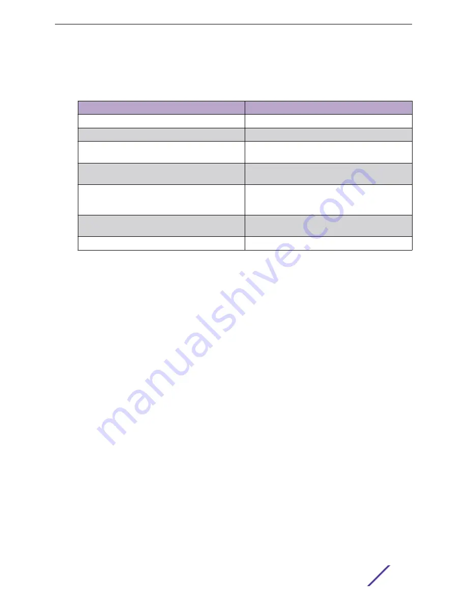
Table 6: Power supply status LED indicator patterns
Power supply condition
LED pattern
Output On and OK
Green
No AC power to all power supplies
Off
AC present/ Only 12VSB On (PS Off) or PS in cold
redundant state
1 Hz blinking green
AC power cord unplugged or AC power lost, with a
second PS in parallel still with AC input power
Amber
Power supply warning events where PS continues to
operate - high temperature, high power, high current,
and slow fan
1 Hz blinking amber
Power supply critical event causing a shutdown, failure,
OCP, OVP, and fan fail
Amber
Power supply firmware update
2 Hz blinking green
Installing a Redundant Power Supply
To install a power supply module:
1 If the power supply insert is installed, remove the insert from the chassis power supply module #2
bay.
2 Insert the power supply module into the power supply bay.
Hardware Installation
ExtremeCloud™ Appliance E3120
13


