Page 1 PRC50-EN-V2.1 11/11
User Guide
Multifunction Process Calibrator
Model PRC50
Page 1: ...Page 1 PRC50 EN V2 1 11 11 User Guide Multifunction Process Calibrator Model PRC50 ...
Page 2: ...ter frequency and pulse Additional features z Manual step source auto step and sweeping step source z Measure source mA display z Wave filter function z Manual hold function 2 Standard Accessories Ensure that the package contains all of the accessories listed below If items are damaged please contact the vendor from which the product was purchased z One 1 set of Industrial Test Leads z One 1 set o...
Page 3: ...or cracks or missing plastic Pay particular attention to the insulation surrounding the connectors z Select the proper function and range for the measurement z Make sure the battery door is closed and latched before operating the meter z Remove test leads from the meter before opening the battery door z Inspect the test leads for damaged insulation or exposed metal Check test lead continuity Repla...
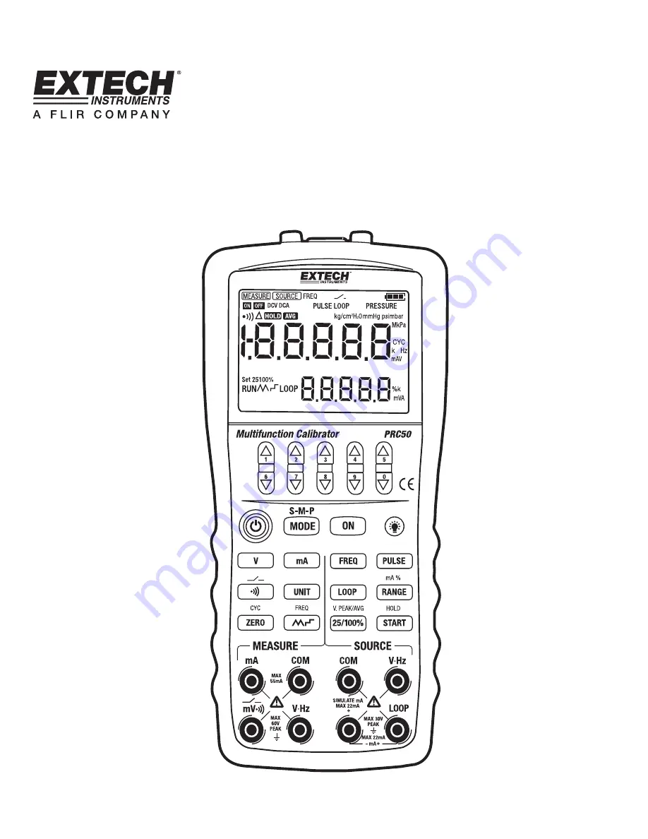
Page 4: ...ment terminals 5 Source terminals Figure 1 Meter Description 4 1 Measurement Source Terminals Figure 2 shows the calibrator s measurement source terminals Table 2 explains their use Figure 2 Measurement Source Terminals Table 2 Measurement Source Terminals Terminal Function 1 Measurement Signals DCmV 2 Measurement Signals DCV FREQ 3 Measurement Signals DCmA 4 Common return terminal for all measure...
Page 5: ...SE Key Select source pulse function 17 mA Key Select measurement source mA function 18 FREQ Key Select measurement source FREQ function 19 Key Select measurement continuity function 20 RANGE Key Select measurement source range mA percentage toggle key 21 UNIT Key not used 22 LOOP key Switch ON OFF 24V Loop power 23 ZERO Key Set the source value to its default value In pulse source function set the...
Page 6: ...ource pulse k 24V Loop Power Supply ON l Not used m Beeper for measurement continuity n Not used o Measured value HOLD p Measurement average value q Not used r Main numerical display s Unit of measure for main display t DCmA 25 or 100 manual step source u Start source number of pulses DCmA auto stepping or sweeping source function v 24V Loop Power Supply ON w DCmA auto stepping or sweeping source ...
Page 7: ...f the battery holder opened Environmental Requirements Use the instrument in locations that meet the following environmental requirements z Ambient temperature range 32 to 122o F 0 to 50o C ambient humidity range 20 to 80 RH non condensing z Place the instrument on flat and level areas Do not use the instrument in locations that are z Exposed to direct sunlight or close to any heat source z Expose...
Page 8: ...e batteries and or fuses refer to Section 12 of this User Guide Switching Power ON Press the Power key once to switch ON the calibrator Press and hold the Power key for 2 seconds to switch it OFF Automatic Power OFF When the calibrator is running on batteries and no key is pressed for approximately ten minutes the calibrator switches OFF automatically The automatic power off time can be programmed...
Page 9: ...ircuitry may be damaged 5 1 Connecting Cables to Terminals For DC voltage frequency or pulse see Figure 5 Step 1 Connect the black lead cable for source to the COM output terminal and the red lead cable to the Vhz output terminal Step 2 Connect the other ends of the cables to the input of equipment under test while making sure the polarities are correct Figure 5 Sourcing DC voltage frequency and p...
Page 10: ...tage between the output terminals Step 4 To turn off the output press the ON key again The OFF icon appears on the LCD and no signals are sourced between the terminals 5 3 Sourcing DC Current Step 1 Use the mA key to select the desired source function 20mA The default value and unit of the selected source function will be displayed on the LCD Step 2 Set the output value digit by digit using S T ke...
Page 11: ... 20 mA range within which to source current in 4 20mA increments or decrements in auto stepping mode or in auto sweeping mode 80 seconds are required to finish a 4 20mA cycle in auto sweeping mode and 20 seconds are required for auto stepping mode Step 1 In the DC current mode press the key to display the auto stepping mode signal on the lower part of the screen and press it again to display the a...
Page 12: ...put value digit by digit using each pair of S T output setting keys Each pair of S T keys corresponds to each digit of the LCD reading Each press of the S T key increases or decreases the digit Increasing the digit from 9 or decreasing it from 0 causes the digit to overflow or underflow allowing the output value to be set without interruption Holding down the S T key continuously changes the digit...
Page 13: ... it from 0 causes the digit to overflow or underflow allowing the output value to be set without interruption Holding down the S T key continuously changes the digit quickly The value won t change if it is increased or decreased to the Maximum or Minimum value Step 4 Pressing the VPEAK key switches to the amplitude setting mode The LCD shows a reading of 1V Step 5 Set the output value digit by dig...
Page 14: ...appears on the LCD and no signals will be sourced between the terminals Notes z The frequency range of the pulse can only be changed by pressing RANGE in the frequency set mode z When the RUN symbol switches OFF the user can change the frequency and amplitude when the source function is in ON or OFF z During the pulse sourcing process pressing the START key causes the calibrator to switch OFF the ...
Page 15: ...ange the measured value on the LCD indicates oL 6 1 Connecting Cables to Terminals For DC voltage mV and continuity Figure 8 Step 1 Connect the black test lead cable for measurement to the COM input terminal and the red test lead cable to the mV input terminal Figure 8 Measuring DC voltage and continuity Step 2 Connect the other end of the cables to the terminal points of the equipment under test ...
Page 16: ...are in making connections always check the accuracy of the connection configuration z The current input terminals are equipped with a built in current input protection fuse Over current input to the terminals will cause the fuse to blow If the fuse is blown replace it with one with the specified ratings For details on fuse replacement see the Replacing the battery and fuse section Warning Wiring o...
Page 17: ...e equation below 100 current measured value mA 4mA mA 16 mA 6 3 2 Using the Calibrator as a 24 V Loop Power Supply This function helps to switch ON a 24V loop power supply connected in line with the measured DC current circuit in which the calibrator can be used as a loop power supply that can calibrate a 2 wire converter Step 1 When the calibrator is in the current measurement mode pressing the L...
Page 18: ...rement function The LCD displays the continuity symbol on the upper area Connect the device as shown in Figure 8 the beeper will sound continuously if the loop circuit resistance is below 250Ω The LCD shows the circuit OPEN or CLOSED icon 6 6 Measurement filtering function The measurement filtering function stabilizes the measured value displayed on LCD In the DCV or DCmA function pressing the AVG...
Page 19: ...he automatic power off function is disabled 7 2 Setting Backlight time Step 1 Use the MODE key to move to the BL OFF parameter at the top of the LCD if it s not already displayed Step 2 Set the time using the S T keys the unit of measure for the time is seconds and the range is 0 3600 seconds Each pair of S T keys corresponds to each digit of the LCD reading Each press of the S T key increases or ...
Page 20: ...M select DPM using the right pair of S T keys Step 3 To save the setting press the ON key and the LCD will show the SAVE symbol 7 5 Factory default Step 1 Use the MODE key to move to the FACry parameter at the top of the LCD if it s not already displayed Step 2 Press the ON key to revert to the default values as shown below AP OFF 10 minutes BL OFF 10 seconds FRSET 50 Hz CMSET PCM ...
Page 21: ...ype four AAA 1 5V z Remove the batteries if the meter is to be stored for a long period Step 1 Remove the test leads and charger before replacing the batteries or fuses and switch OFF the meter Figure 16 Replacing batteries and fuses Step 2 Remove the rubber protective holster as shown in Figure 16 With a standard blade screwdriver turn each battery door screw a quarter turn counter clockwise to r...
Page 22: ...c lens and case do not use solvents or abrasive cleansers Clean the Calibrator with a soft cloth dampened with a mild soap 9 2 Calibration Repair and Technical Support Services Extech offers repar and calibration services for the products we sell Extech also provides NIST certification for most products Call the Customer Care Department for information on calibration services available for this pr...
Page 23: ...t Resistance 1MΩ DCmA 50mA 4 000mA 55 000mA 1μA 0 02 rdg 0 01 range Input Resistance 5Ω 500Hz 3Hz 500 00Hz 0 01Hz 5KHz 3Hz 5 0000KHz 0 1Hz FREQUENCY 50KHz 3Hz 50 000KHz 1Hz 2 digits Input Impedance 100kΩ min Sensitivity 3Vp p min Duty Cycle 50 CONTINUITY 250Ω beeper Open circuit voltage 2 5V Notes z DCV Normal Mode Rejection Ratio NMRR 60dB at 50Hz or 60Hz Common Mode Rejection Ratio CMRR 120dB at...
Page 24: ...for simulate mA 5V 28V Maximum load 1KΩ at 20mA 100Hz 1 00Hz 110 00Hz 0 01Hz 1KHz 0 100KHz 1 100KHz 1Hz FREQ 10KHz 1 0KHz 11 0KHz 0 1KHz 2 counts 100Hz 1KHz PULSE 10KHz 1 to 100 000cycles 1cyc Output voltage 1 11 Vp p zero based waveform Amplitude accuracy 10 0 5V Maximum load 100 KΩ Duty Cycle 50 LOOP 24V 10 Maximum current 25 mA Short circuit protected Notes z Temperature Coefficient 0 1 times t...