13
3.
Set the switch to ON and run the machine for 30
minutes to ensure that the parts break-in properly.
4. Turn the regulator knob completely counter-
clockwise. The device will fill up until the maximum
pressure is reached and turn off.
5.
Turn the regulator knob clockwise to remove air. The
device will restart at the set pressure.
6.
Turn the regulator knob counter-clockwise to shut off
the air supply and set the switch to OFF.
7. Attach a pneumatic tool to the outlet. Turn the
regulator knob clockwise. Set the device switch to
ON to force the air into the tank. The device will turn
off automatically when it reaches the maximum set
pressure.
NOTE: Make sure the switch is in the OFF position
when connecting or disconnecting the power cord
from the electrical outlet.
STARTING PROCEDURE (applies to models MSW-0AC550-
8L, MSW-0AC750-8L)
ATTENTION! Do not attach pneumatic tools to the air outlet
of the device until start-up is completed correctly.
1.
Set the switch to OFF position and connect the power
cord.
2.
Set the switch to ON and run the machine for 30
minutes to ensure that the parts break-in properly.
3.
Set the switch to OFF and connect a pneumatic tool to
the outlet.
4.
Set the device switch to ON to force the air into the
tank.
NOTE: Make sure the switch is in the OFF position
when connecting or disconnecting the power cord
from the electrical outlet.
MOISTURE IN COMPRESSED AIR
The moisture in the compressed air condenses. When the
humidity level is high or when the device has been working
for a long time, moisture will accumulate in the tank. When
a paint spray gun or sandblasting gun is used, water will be
carried on from the tank through the hose and gun in the
form of droplets mixed with the spray material.
This will cause water stains when painting, especially when
spraying non-water based paints. In the case of sandblasting,
this will cause sand to build up and clog the gun. A filter in
the air line, located as close as possible to the gun, will help
eliminate this moisture.
TANK PRESSURE INDICATOR
The indicator shows the pressure in the tank, indicating
whether the device is generating pressure correctly.
THERMAL OVERLOAD FUSE
IMPORTANT! The compressor is equipped with an automatic
thermal overload protection that will stop the motor in the
event of overheating.
If the thermal overload protection often turns off the motor,
the reasons may be:
1.
low voltage
2.
air filter clogged
3.
lack of adequate ventilation
IMPORTANT! If the thermal overload protection has been
triggered the motor must cool down before it can be started.
The motor will restart automatically without warning if the
machine is left turned on and connected to an electrical
outlet.
3.4. CLEANING AND MAINTENANCE
IMPORTANT! Disconnect the machine from the power
supply, then release all pressure from the system and allow
the device to cool before cleaning it, repairing, transporting
or performing any maintenance.
a)
Use only non-corrosive cleaners to clean the surface.
b) After cleaning the device, all parts should be dried
completely before using it again.
c)
Do not spray the device with a water jet or submerge
it in water.
d)
Do not allow water to get inside the device through
vents in the housing of the device.
e)
Clean the vents with a brush and compressed air.
f)
The device must be regularly inspected to check its
technical efficiency and spot any damage.
g)
Use a soft cloth for cleaning.
MAINTENANCE
Once a week:
1.
Drain moisture from the tank by opening the drain
valve under the tank. Otherwise the tank may corrode.
2.
Remove dust and dirt from the motor, tank, air hoses
and cooling ribs of the device.
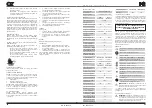
ON
OFF
ON
OFF
12
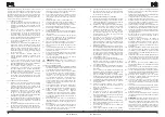
3.2. PREPARING FOR USE
3.2.1. APPLIANCE LOCATION
The ambient temperature must not exceed 38°C. The device
should not be used at temperatures equal to or lower than
0°C, because moisture accumulating in its tank may freeze
and ice may block and damage the valves.
Ensure good ventilation in the room in which the device is
being used. There should be at least 45 cm distance between
each side of the device and the wall or other objects. The
device should always be used when positioned on an even,
stable, clean, fireproof and dry surface, and be out of the
reach of children and persons with limited mental and
sensory functions. Position the device such that you always
have access to the power plug. The power cord connected
to the appliance must be properly grounded and correspond
to the technical details on the product label. The electrical
socket, which the device will be connected to, must be
grounded and fully functional. Do not use electrical outlet
adapters with this device! The electrical wiring system to
which the device will be connected must be equipped with
a slow-blow fuse or circuit breaker.
NOTE: Never use an extension hose with this product. Use an
additional air hose instead of an extension hose to avoid loss
of power and permanent damage to the engine.
NOTE: The compressor air inlet must be away from steam,
paint spraying area, sandblasted areas or other sources of
contamination. These impurities will damage the engine or
clog the filter.
Handling in the workplace
When handling in the workplace, use the carrying handle.
NOTE: Never use the handle to completely lift the machine
off the ground on wheeled models.
3.3. DEVICE USE
ON / OFF pressure switch
In the ON position, the compressor switches off automatically
when the pressure in the tank reaches the maximum set
pressure. In the OFF position, the compressor will not work.
This switch should be in the OFF position when connecting
or disconnecting the power cord from the electrical outlet
or when changing pneumatic tools / devices connected to
the compressor.
STARTING PROCEDURE (applies to models MSW-0AC550-
24L, MSW-0AC750-24L)
ATTENTION! Do not attach pneumatic tools to the air outlet
of the device until start-up is completed correctly.
1.
Turn the regulator knob completely to the right to
open the airflow.
2.
Set the switch to the OFF position and connect the
power cord.
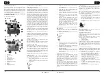
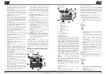
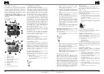
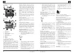
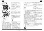
1.
Air inlet
2.
Delivery pipe
3. Handle
4.
ON / OFF switch
5.
Tank pressure indicator
6.
Safety valve
7.
Check valve
8.
Moisture drain valve
9. Tank
10. Regulator
11. Air outlet
12. Outlet pressure indicator
SAFETY VALVE
The safety valve automatically releases air if the pressure
in the tank exceeds the set maximum. WARNING! Do not
remove or attempt to adjust the safety valve!
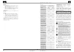
CONTROLLER KNOB (MSW-0AC550-24L, MSW-0AC750-24L
models only)
The regulator knob controls the air pressure supplied to the
output pneumatic tool.
•
To increase the outlet air pressure, turn clockwise.
After reaching the desired pressure, lock with nuts.
•
To reduce the outlet air pressure, turn counter-
clockwise.
•
To completely cut off the airflow, turn fully counter-
clockwise and press the knob.
LUBRICATION
Oil-free compressors do not require lubrication.
STORAGE
1.
Remove moisture from the tank before storage.
2.
Disconnect the hose and hang its open ends down to
allow moisture to drain out.
3.
Store the unit in a dry, cool place, free from moisture
and direct exposure to sunlight.
If you cannot avoid storing the device at a temperature equal
to or lower than 0°C, ensure that it is free of moisture and
dry.
Rev. 25.09.2019
Rev. 25.09.2019


