


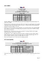


F-4 Clockable AD Envelope & VCA
X is clock input
Y is VCA input
Z sets the envelope shape
A is envelope output
B is VCA output
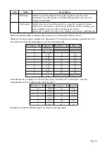
Tap tempo enabled
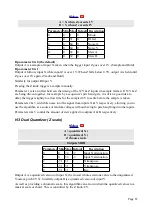
Parameter Min Max Default
Description
0
-15 8
0
Delay time multiplier.
1
-40 41
32
Output A Attenuverter.
2
-40 40
32
Output B Attenuverter.
3
0
32
26
Attack shape.
4
0
32
10
Decay shape.
This algorithm is a two-stage (attack/decay) envelope generator, whose overall time is set from an
input clock pulse. The envelope is continuously output (starting on each new clock pulse). This
algorithm also offers a VCA (voltage controlled amplifier) function.
Input X is the clock input. Any clock pulse in excess of 1V can be used. The time between rising
trigger edges is used to set the envelope time.
Parameter 0 applies a multiplier to the envelope time, according to the table above.
Input Y is the VCA input. The signal here will be multiplied by the envelope and output on output
B.
Z sets the envelope shape, from short attack & long decay, to long attack and short decay.
Parameters 3 & 4 set the attack and decay shapes of the envelope respectively, from an exaggerated
exponential curve at 0 to an almost linear shape at 32.
Output A is the envelope CV, and output B is the VCA output as mentioned above. Parameters 1 &
2 are attenuverters, which can attenuate and/or invert the signal for each output independently. The
unattenuated envelope level is 8V; output B is unity gain with respect to input Y if unattenuated.
If parameter 1 is set to the special value 41, output A becomes an end-of-cycle trigger output,
generating a 10ms 5V pulse at the end of the envelope's release stage.
F-5 Shift Register Random CVs
Page 53


